|
»Click here to display Table of Contents«
|

Section Editor |

|

|

|

|
|
Section Editor |
|
|
|

|
|
»Click here to display Table of Contents«
|
Section Editor |
|
|
|
|
|
Section Editor |
|
|
|
|
The Section Editor can be started from the Section Edit panel. Once you have selected a cross section based on elements, lines, or surfaces, click edit section to open the Section Editor. (You can also click the Edit Section macro on the Die Module Utility Menu.)
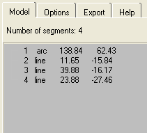
The original cross-section geometry is shown with a green line. The changes you make in the Section Editor are represented by a blue line that initially matches the green line before you make any changes. The Section Editor automatically breaks down the cross-section geometry into discrete segments including arcs and lines. These segments are numbered and listed on the left side of the dialog. When you click one of the segments in the list, the corresponding portion of the line is highlighted in white in the graph on the right side of the dialog. An example is shown in the following image.
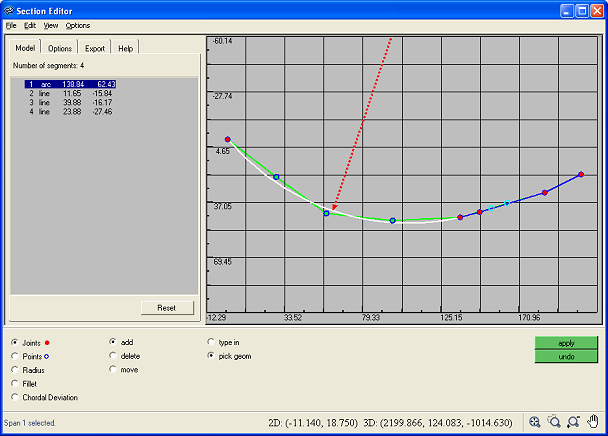
Line segments in the list show the corresponding length and angle, in that order. Arc segments show the radius and arc angle, in that order.
There are various manipulation options available in the lower section of the dialog under the Local Operation and Global Operation option groups:
Option |
Description |
||||||
Joints |
Select this option to add, delete, or move joints on a segment. Select the Joints option and the either the add, delete or move sub-option.
|
||||||
Points |
This option is active when you have a segment selected. Points are automatically created when you open the Section Editor at locations where the section intersects the mesh. Select either type in or pick geom sub-option as the method of specifying the location of a new point.
|
||||||
Radius |
This option is available when you have a segment selected. Click and drag on the graph to change the shape of the segment. The radius of the segment is shown in the dialog and the model in HyperForm is updated when you release the mouse button. |
||||||
Fillet |
Select this option to smooth out sharp corners in the section. You can smooth out corners by individual joints or the entire section at once with the at point and global sub-options.
|
||||||
Chordal Deviation |
Select this option to control the tolerance used in creating the joints and points in the initial cross-section geometry. Type a new chordal deviation value in the Chordal Deviation field and click apply. The joints and points are adjusted based on the new value and general shape of the section changes. Choose smaller chordal deviation values for complex sections. Smaller values result in an increased number of joints. |
The Section Editor includes several display options. These options can be selected on the Options tab in the left panel of the dialog. The following options are available:
Option |
Description |
Show original lines |
Controls whether the original section line (green line) is displayed on the graph. |
Show scales |
Controls whether scale labels are shown on the graph axes. |
Show circle and center for arc |
Controls whether circles and center points display for arc segments. |
View
Option |
Description |
Show arrow and center for all |
Display arrows and centers for all arcs. |
Show arrow and center for selected |
Display the arrow and center for the currently selected arc. |
After modifying a section in the Section Editor, you can export the section as a rib to be used in the creation of an addendum. To export a rib, click the Export tab in the Section Editor.
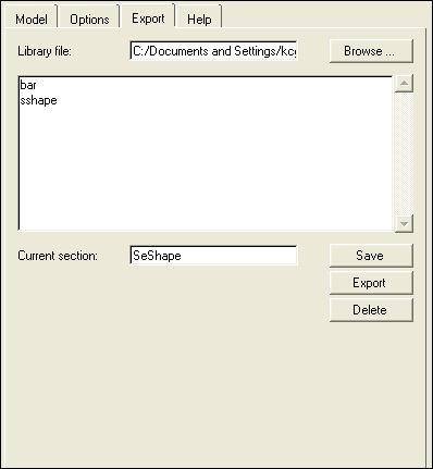
Rib definitions are stored in a library file named hf_riblib.data by default in the Windows Documents and Settings folder. This file name and path is automatically listed in the Library file field on the Export tab. Click Open and navigate to another location if you want to store the rib in a library other than the default.
The existing ribs in the library are listed in the box. Type a name for the rib you want to create in the Current section field and click Save. The new rib appears in the library list. To delete a rib from the library, select it in the list and click Delete.
Click Export to export the rib to the specified library file.