The Melt Flow Analysis Wizard is used to set up models for polymer flow analysis. In order to use this tool, the CAD model must be made of solids and these solids should share the common surfaces. Inserts can be modeled with solids or via insert surface boundary conditions. Since you are prompted to pick the inlet, outlet, and insert surfaces, this wizard can be used to setup models for a variety of processes.
When you click on the Melt Flow Analysis button, it opens the Project Browser tab, where you can select and load the project. Select or create a new run and load the model to the Project Browser. This will invoke the Wizard tab. If you have already loaded a model, click Melt Flow Analysis. For more information, please refer to the Project Browser section in this user's guide.
You must complete each one of these simple steps, one at a time, to complete the model setup. No knowledge of HyperMesh is necessary to complete the steps.
Melt Flow Analysis Tab
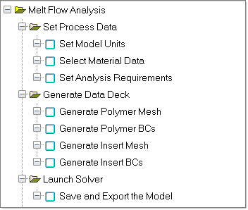
The steps used to create the data deck are represented using check boxes. These steps are:
| - | Select the material data |
| - | Set the analysis requirements |
| - | Save and export the model |
|
|
The steps completed and the status is indicated in the project message bar. Click Summary to display information regarding process conditions, materials selected, boundary conditions created and element statistics. Click Close to close the tab and return to the Utility menu.


