Option
|
Description
|
offset / offset+planes / offset+planes+sweeps
|
| • | Choose offset to create pieces of the middle surface by offsetting the model's side surfaces towards the middle. This is the traditional approach for midsurfacing in HyperMesh. |
| • | Choose offset+planes to use a midsurfacing algorithm to identify the places in the model where a piece of plane can be used as a middle surface. At the remaining places in the model, for example the places where planar pieces cannot be used as a middle surface, the same algorithm as in the offset option is used to construct the middle surface via the offset of the model's sides. |
| • | Choose offset+planes+sweeps to use a midsurfacing algorithm to identify the places where a piece of plane or a piece of a sweep surface can be used as a middle surface. A middle surface is constructed at the remaining places in the model, for example the places where planar or sweep surface pieces cannot be used as a middle surface, by the same algorithm as in the offset option via the offset of the model's sides. |
Surface pairing is automatic, and pairs can be further organized using the Plate edit panel.
|
align steps/keep jump steps
|
This is available only when you select offset. In the case of a part that has different "steps" of thickness, such as a flat sheet that is twice as thick at one end as the other but uses an abrupt step-like change in thickness instead of a constant slope or curve, the align steps option will align midsurfaces whereas keep step jump will produce steps between the various midsurfaces as in the original model.
The image for auto mid position / user mid position, below, shows such a case.
|
auto mid position / user mid position
|
This is available only when you select offset and align steps. If you select auto mid position, HyperMesh will create a midsurface parallel to the largest side of the volume. This midsurface includes "offset" data to represent the changes in distance between the midsurface and the smaller faces at each "step".
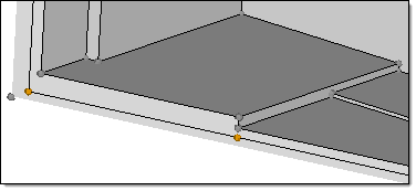
The midsurface (with orange nodes) is parallel to the larger face of the solid plate
If you select user mid position, you have to define the offset of the midsurface, using a value from 0 to 1, to specify the offset from the largest side of the volume.
|
allow rerun
|
Adds the rerun option to the Auto Midsurface panel.
|
use base surfaces
|
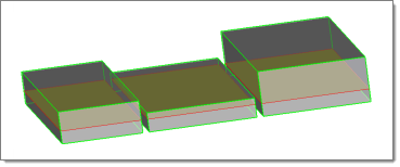
In some cases, you may need to extract midsurfaces from multiple solids as if they were a single solid using the align steps option.
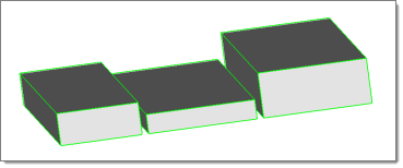
Normally, this would result in multiple midsurfaces, each one at the middle of the solid it was extracted from (and therefore not aligned with each other). The use base surfaces option allows you to select the separate-but-aligned faces that you wish to treat as if they were continuous (in the image above, these would be the three bottom faces) and create the multiple midsurfaces based on them.
When this checkbox is active, a new base surfaces setup button displays on the main auto midsurface subpanel. Clicking this button opens a temporary panel that allows you to select the desired surfs and specify a distance to base. When you add these base surfaces, new midsurfaces are created at the specified distance from the selected base surfaces.
You can perform this action multiple times, each time selecting different sets of base surfaces and distances.
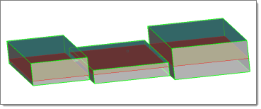
You can also use this feature to create aligned midsurfaces for non-aligned solids, by specifying each solid and its offset separately, using a different offset for each (obviously you must know the exact dimensions of each solid to do this accurately):
| Note: | If the base surfaces are set but the use base surfaces checkbox is later unchecked, the base surfaces will not be used, though their setup will be kept as long as it is not explicitly deleted by you (so it can be used later, if needed). |
If both align steps and use base surfaces are used for the same solids, the base surface distance will overwrite the align steps distance.
Be careful to set the base surfaces correctly. In particularly, if both sides of a plate are selected as the base surfaces, which one of the two will be actually used is random.
|
thickness bounds/
no thickness bounds
|
This option allows you to set the minimum and maximum thickness of the plates in the part. If thickness bounds are specified, middle surfaces are only created for plates with a thickness that falls into the specified range. This option can improve the robustness of the results and speed up middle surface creation; however, you must be sure that you do not cut off some plates by selecting thickness limits that are too narrow.
If you choose no thickness bounds, midsurface extraction still uses the max thickness ratio.
|
max thickness ratio
|
This is the highest acceptable ratio of the thickest plate’s thickness to that of the thinnest plate. Plates whose thickness is greater than this value multiplied by the thinnest plate’s thickness will be ignored.
Using too small a value can cause incorrect midsurface extraction. However, larger ratios take more time to process.
|
max R/T ratio
|
This ratio is taken into account on T-, X- and more complex connections only, as in the picture below. On a curve without a T-connection (like on the right side on the picture) it does not apply.
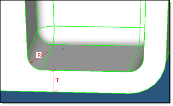
If R/T is greater than the specified value, then this location will not be recognized as a junction and will be considered as a solid piece. If T is different on different sides on the junction (as in the above picture), then the maximum T is used.
Since in many cases the fillet is not an exact cylinder and has a variable curvature, or the fillet cross-section is not orthogonal to the fillet axes, in reality the length on the curve at the fillet is taken and R is recalculated from this length as if it were an arc of a circle.
Previously, this parameter was only used internally and was set at a value of 2.0.
|
thickness based stitch tol
|
When the thickness based stitch tol checkbox is active, the final stitching of midsurfaces is performed with a locally-defined tolerance of 1/5 of the local thickness (which was the default in the previous HM versions).
If unchecked, global cleanup tol from the Options panel is used for stitching. This method is recommended when an extensive manual edit of the automidsurfacing result is expected, because stitching comparatively distant midsurfaces may misrepresent the geometry of the model and affect following operations on geometry.
|
extract by component/cross components
|
This option is useful when you are trying to extract the midsurface of multiple parts in a single step. If it is toggled to extract by component, it assumes that each part is contained in its own component, so it extracts the midsurface of one component at a time. If your model contains a single part organized in multiple components, you should toggle this option to cross components.
|
result in Middle Surface comp/result in current comp / sorted results
|
This toggle specifies if the midsurfaces are created in the Middle Surface component (created if it does not exist) or in the current component. It is recommended to use the result in Middle Surface comp setting.
|
sort Middle Surface comp into
|
This option specifies how to organize the midsurfaces generated in the Middle Surface component when the sort button is clicked.
The <~[o]riginal name> comp option creates new components by removing the first letter of the original component name and replacing it with a ~ and sorts the midsurfaces accordingly. For example, my_comp -> ~y_comp.
The <Midsurface #nn> comp option creates components with the name Midsurface #, where # increases for each component that exists for the input surfaces/solids.
The original comp option organizes the midsurfaces into their parent surface/solid components.
|


