Non systematic method enables the analyst to setup a 2D
free-size topology optimization to highlight the load paths and areas to reinforce.
Often, an interpretation to feasible design is required by the design and manufacturing
team.
Optimization Deck Setup
Below is an illustration of Non Systematic Optimization
setup workflow-Figure 1.
Below is the Non Systematic optimization setup panel-Figure 2.
Problem Identification
Select the loadcase from Loadcase Selection and
required E-Line from Select E-Line lists.
Choose the Optimization Direction.
Click Load.
This loads the model, post processing results, selected loadcase and
E-Line into the session. HyperView window splits into four:
.H3D file of MTRAN analysis, showing selected interface and all 2D
Parts.
Relative displacement graph for selected interface.
Relative Modal Contribution bar chart.
.H3D file of Modal Analysis.
Optimization Set up
Check Auto Select box.
This automatically selects the E-Line interface components from the
list.
Thickness values are auto filled based on the components selected. You
have the option to edit the values.
Optional: Click Components
button to select components manually from the graphics area.
Optional: Click Review
Selection.
This isolates the interface and components in the graphics area.
Select the required frequency from the Frequency range
selection table.
Check Auto Fill box.
This auto fills the Min. (Hz) and Max.
(Hz) value fields. If only one frequency is selected,
Single Freq. (Hz) is auto filled.
Non Systematic Optimization Options
Loadcase Selection
Lists all the loadcases present in the results file.
Select E-Line
E-Line interface which you want to optimize.
Optimization Direction
Select the optimization direction.
This selection must be based on the information shown in the
Relative Displacement or Line
Graph.
Components
Components that you want to optimize.
Only 2D PSHELL parts must be selected.
Thickness Values
Minimum and Maximum thickness values.
These are picked from the properties of selected components.
Frequency
Identify frequency(s) to optimize the components for.
Frequency table will be empty for static loadcase.
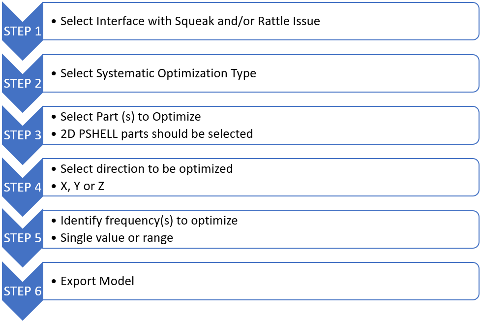 Figure 1.
 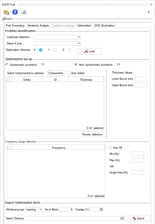 Figure 2.