HM-3680: Preserve a Shape With Cluster Constraints
In the tutorial, you will be changing the length of the cab while preserving the shape of the wheel. To facilitate the morphing process you will be employing constraint and symmetry.
When circular features are stretched, they become elliptical in shape. In some cases as in the wheels of a truck, this effect is not desirable. In such cases, using cluster constraints will allow you to translate the features, along with the morph, while maintaining its circular shape.
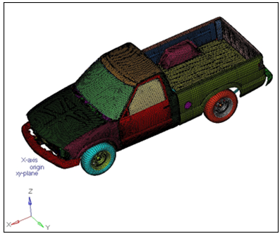
Figure 1.
Open the Model File
In this step, you will open the model file, truck.hm.
- Open the model file, truck.hm.
- Review the model.
Create a Coordinate System
In this step, you will create a coordinate system.
-
On the toolbar, select XZ Right Plane View (
 ).
).
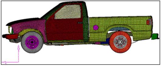
Figure 2.
Create and Split Morph Volume
In this step, you will create and split the morph volume.
-
Click create to create the morph volume.
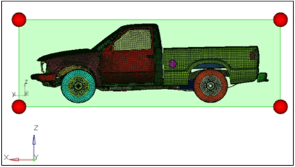
Figure 3.
Create a Symmetry
In this step, you will create a symmetry.
-
Click create to create the symmetry.
A 1 plane symmetry with a square symbol is created.
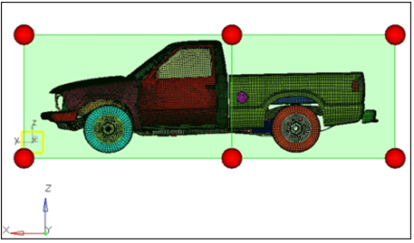
Figure 4.
Morph the Part
In this step, you will morph the part.
-
Click morph to morph the front half of the truck.
The front end is stretched 500 units. Since the front wheels are also the part of the morph volumes they became elliptical after morphing. This is not desirable. You will undo this morphing, constrain the wheels and re-do it.
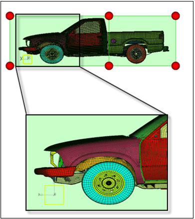
Figure 5.
Create a Cluster Constraint
In this step, you will create a cluster constraint.
The front wheels, after morphing, become elliptical. To fix this issue, you will be employing a particular type of constraint, called a cluster constraint, which helps to keep the original shape of a portion of the model while morphing.
-
Click create to create the cluster constraint.
The cluster constraints are created on the nodes of the selected components.
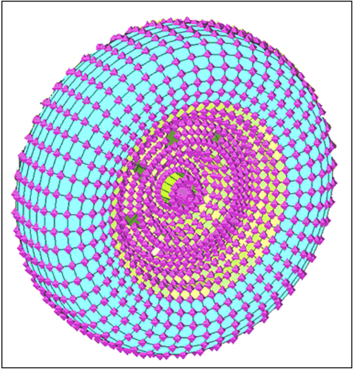
Figure 6.
Morph the Part
In this step, you will morph the part.
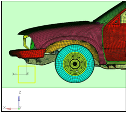
Figure 7.
Using cluster constraints and morph volumes you are able to stretch the cab of the pickup without distorting the wheels.