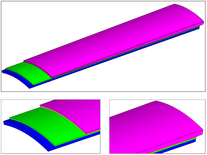
In this tutorial, you will use morphing to change the thickness of the middle layers
of a four-layered solid, while maintaining the thickness of the outer layers.
Domains will be created using 3D domains > by component. Thickness will be altered using
alter dimensions.
This exercise uses the Morph_Adhesive_Layers.hm file, which can be
found in the hm.zip file. Copy the file(s) from this directory to
your working directory. Figure 1.
Open the Model File
In this step you will open the model file,
morph_adhesive_layers.hm.
Open the model file, morph_adhesive_layers.hm.
Create Domains and Handles
In this step you will create domains and handles.
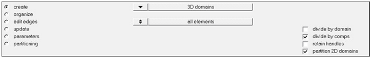
Click the Morphing menu and select Create > Domains.
Switch the domain type to 3D domains.
Toggle the element selector to all elements.
Activate the divide by comps and partition 2D
domains options.
Figure 2.
The panel appears.
Click create to create the domains.
Click return to exit the Domains panel.
Display Morph Faces
In this step you will display only the morph faces of interest.
Using the Model Browser, hide all components except
^morphface.
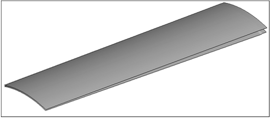
Mask all ^morphface elements except those on the outer layer and the layer
between the Outer comp and the Adhesive_Outer to leave all the elements as shown
in the following image.
Note: Select a couple of elements on the face you want to keep. Select
elements >> by face, and then select
elements >> reverse. This will reverse the
selection to the elements you do not want and will allow you to mask those
elements with the mask button. Figure 3.
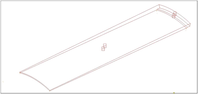
To reduce the number of domains and handles shown on the screen, click the
Mask tab.
Click the + next to Morphing to expand it.
Click the + in the Show column for Local Domains/Handles
to display the domains and handles for only the displayed elements.
Hide the ^morphface component in the Model Browser.
Figure 4.
Increase Thickness of Outer Adhesive Layer
In this step you will increase the thickness of the outer adhesive layer by 5
units.
Click the Morphing menu and select
Morph to open the Morph panel.
Open the alter dimensions subpanel.
Change the dimension type to radius.
Activate the add to current checkbox.
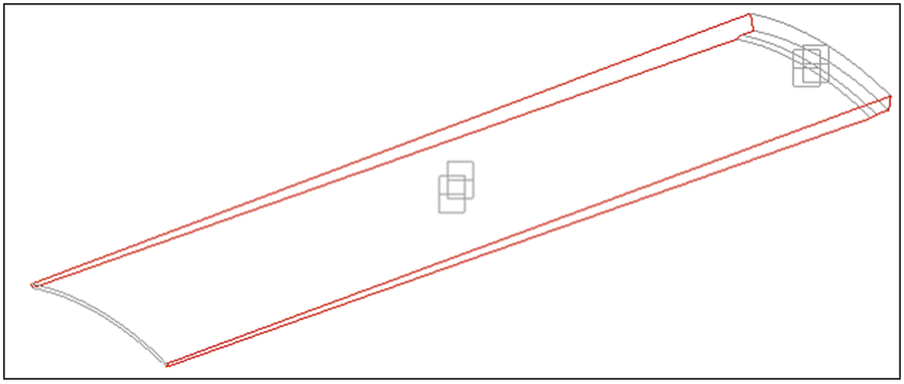
For domains, select the curved edge domains as well as the 2D domains
representing the curved surfaces as seen in the following image.
Figure 5.
Set the center calculation to by axis.
For the axis, use the z-axis.
For B select the temp node that represents the center of the cylinder.
In radius= box, change the value to 5 units.
Click morph.
Go to the save shape subpanel.
For name=, type sh1.
Switch to as node perturbations.
Click save.
Click undo all to revert back to the original model
configuration.
Show all components except the ^morphface component.
Go to the apply shapes subpanel.
For shapes, select sh1.
Click select.
Click animate. This takes you to the Deformed Shape
panel.
Change the animation scale from model units to
scale factor.
Set the scale factor to 1.
Click linear to start the animation.
Once you are done viewing your animation and verifying that it is as intended,
you can return to the main panel area.
Optional: Using the process above, increase the thickness of Adhesive_Inner component by
5 units.