BasicFEA

Solid Edit panel

Solid Edit panel

Previous topic Next topic Expand/collapse all hidden text  

Solid Edit panel

Previous topic Next topic JavaScript is required for expanding text JavaScript is required for the print function  

Use the Solid Edit panel to modify solid entities. For example, you can trim and/or split solids, as well as merge solids into a single entity.


Subpanels and Inputs


The Solid Edit panel contains the following subpanels:

hmtoggle_arrow1Trim with Nodes

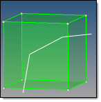
Use the Trim with Nodes subpanel to trim solids based on nodes that you pick. The nodes must define an enclosed cross-sectional surface, but this surface need not be planar.

Multiple solids can be trimmed using the same set of nodes; each solid is trimmed according to the surface defined by those nodes, provided that this surface intersects each solid.  However, BasicFEA only creates new surfaces within the solids—so, for example, if your nodes define a large plane that intersects two cubes, BasicFEA will only create surfaces within the cubes (and thus trim them)—it will not create a single surface filling the entire area enclosed by the nodes.

Clicking trim will trim the selected solids along the 2-dimensional surface bounded by the nodes or points that you selected.  Gaps between solids do not acquire a surface.

trimsolid_multiplesolids

This example used 4 nodes: 2 at the outer edges of each cube

trimsolid_multiplesolids

This example uses a single cut.


Panel Inputs

Input

Action

solids / surfs selector

solids: select each solid directly by picking it in your model, or by using the extended entity selection menu.
surfs: select each solid by choosing one of its surface faces (either by picking the surface in the model, or using the extended entity selection menu).

nodes list / points selector

This determines how you define your 2-D cutting plane (or non-planar surface).

node list: select 3 or more nodes from FE mesh to define your desired cut.
point list: select the points from model geometry that enclose the cut.

extend trimmer

When this option is active, the trimming operation will extend beyond the boundaries of the nodes, or lines that you used to define it.


hmtoggle_arrow1Trim with Lines

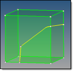
Use the Trim with Lines subpanel to select lines from your model to define the edges of a trim plane.

Three different methods of line-based trimming exist on this panel, separated into three different columns: with cut line, with bounding lines, and with sweep lines.

Cut Lines refers to creating a cut through the solid along a line that you draw with the mouse.

Bounding Lines refers to the process of choosing lines from the model geometry that define a plane or other 2-D area.  The solid is then cut along this plane.

Sweep Lines refers to selecting lines in your model and then extending those lines to create 2-D cutting surfaces.  Thus, you can "sweep" the lines through your model, either along a specified vector or to one or more end points, to define the cuts.


Examples


The selected solid entity is cut along the line segment(s) that you laid down.

solid_edit_cutline_cube_nooptions

solid_edit_cutline_cube_rotated

The same cut, rotated slightly

Note:The angle of the cut depends on the viewing angle of the model; the cut line is extended directly "back" into the viewing area, as if the line were actually the edge of a plane that is perfectly edge-on relative to your viewpoint.  In other words, the cut is normal to your monitor screen, rather than to any surfaces across which you might have dragged the cut line.


Panel Inputs

Input

Action

with cut line: solids selector

solids: pick the desired solid(s) in your model.

surfs: select the desired solids by picking the surfaces associated with them in your model.

The boundaries of each surface highlight, even though the surfaces themselves are not selected.

Note:Regardless of the method, you are still selecting solid entities to trim.

drag a cut line

In the graphics area, use the mouse to draw your cut line:

solid_edit_cutline_cube

smooth line

Creates a curved line that passes through the points you specify.

solid_edit_cutline_cube_smooth

close line

Creates a closed loop, automatically connecting the first and last points that you specify.

solid_edit_cutline_cube_smooth_closed

with bounding lines: solids selector

solids: pick the desired solid(s) in your model.
surfs: select the desired solids by picking the surfaces associated with them in your model.

The boundaries of each surface highlight, even though the surfaces themselves are not selected.

Note:Regardless of the method, you are still selecting solid entities to trim.

with bounding lines:lines selector

Pick the lines in your model that define the desired cutting plane.

trimsolidwithboundinglines_b4

In this example, the top and bottom lines are selected (white)

The selected solids are split along the plane bounded by the chosen lines.

trimsolidwithboundinglines_after

with bounding lines: extend trimmer

When this option is active, the trimming operation will extend beyond the boundaries of the nodes, or lines that you used to define it.

with sweep lines: solids selector

solids: pick the desired solid(s) in your model.
surfs: select the desired solids by picking the surfaces associated with them in your model.

The boundaries of each surface highlight, even though the surfaces themselves are not selected.

Note:Regardless of the method, you are still selecting solid entities to trim.

with sweep lines:lines selector

Pick the lines that you wish to sweep.  These lines, plus their destination, determine the shape and orientation of the cut.

Click trim.

BasicFEA sweeps the selected line(s) along the specified vector or through the specified nodes, splitting the entity along this path (which is frequently not planar when using "end" nodes).

trimsolidwithsweepline_after

This example used the "sweep all" option, so the surface sweeps past the nodes.

with sweep lines:sweep to

Choose between 1 or 2 end nodes or sweeping by a vector.

with sweep lines:
Sweep all /
Input field /
N2 - N1

Sweep all means that the lines sweep completely through the selected solids.
Input field enables a length field, so that you can specify how far to sweep.
N1-N2 sweeps the distance between the N1 and N2 nodes selected in the plane and vector selector (disabled if you used a different option to define the vector).

trimsolidwithsweepline_b4

Here, the line behind the cylinder is selected, and the green and blue nodes are N1 and N2.


hmtoggle_arrow1Trim with Plane/Surf

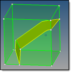
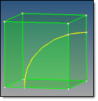
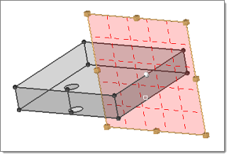
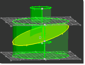
Use the Trim with Plane/Surf subpanel to trim solid geometries using a plane or other trimming surface.

Sometimes a single solid entity has feature lines that could be extended into surfaces, thereby splitting the entity into two different solids. This can be advantageous when trying to mesh solids that have complex shapes.

trim_solid_with_plane


Panel Inputs

Input

Action

with plane: solids / surfs

Use this switch and selector to pick the entities that you wish to trim.  If you pick surfaces, the related solids are selected.

When trim with planes is active, a fill cuts mode is turned on and used. Fill cuts is a special mode of surface trimming. A virtual trimmer surface is created and used to calculate and create new edges on selected surfaces. An attempt is made to insert pieces of this trimmer surface into the body when trimming of the trimmer itself by selected surfaces creates closed loops and thus cuts off those pieces. This is used to simulate solid trimming in cases when you cannot, or do not want to, create solids, but still wants to make solid-like cuts. 
 
This mode is not intended when selected surfaces are solid surfaces themselves. When attempting to insert pieces of a trimmer surface into a solid body, you may also need to manually select other surfaces in order to avoid topologically invalid results. If you do not make this selection completely correctly, the expected result will be undefined. 

with plane: (plane and vector selector)

Use the switch to choose how to define your cutting plane:

If you choose to use the x, y, or z axis, or a pre-defined vector entity, BasicFEA creates the cutting plane normal to that axis or vector.  You must pick a node in your model for base point to indicate at what point in the model the cutting plane intersects the chosen axis or vector.
If you choose the N1, N2, N3 option, pick these three nodes in your model to define the cutting plane.  A base node is not necessary.
If you choose X-edge, clicking an edge of the solid draws a planar manipulator normal to (and centered around) that edge:

solid_edit_xedge

You can change the dimensions of the manipulator by left-clicking-and-dragging the gold handles (this allows you to avoid accidentally trimming additional parts).

You can reposition the manipulator along the length of the edge by dragging the white centroid.

with surfs: solids / surfs (switch)

Use the toggle under the heading with surfs to choose between selecting solids or surfs.

If you choose solids, pick the desired solid(s) in your model.
If you select surfs, then you can select the desired solids by picking the surfaces associated with them in your model.

The boundaries of each surface highlight, even though the surfaces themselves are not selected.

Note:Regardless of the method, you are still selecting solid entities to trim.

trimsolidwithsurf_2

This entire structure is a single solid (selected)

with surfs: surfs (standalone selector)

Click the surfs selector to highlight it, then pick the surfaces in your model that you wish to extend.

trimsolidwithsurf_3

Only the outer curve of the cylinder is selected.

trimsolidwithsurf_4

When you click trim, The cylindrical
surface extends to split the solid.

with surfs: extend trimmer

When this option is active, the trimming operation will extend beyond the boundaries of the input surface when the surface is not part of any selected solid.  If the input surface is part of a selected solid, the trimmer is always extended in order for the operation to be relevant, regardless of the status of this option in the GUI.


Comments

This process uses the *body_splitmerge_with_plane command or *trim_solids_by_surfaces command, as appropriate.


hmtoggle_arrow1Merge

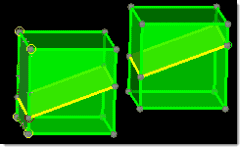
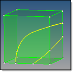
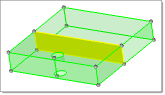
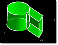
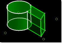
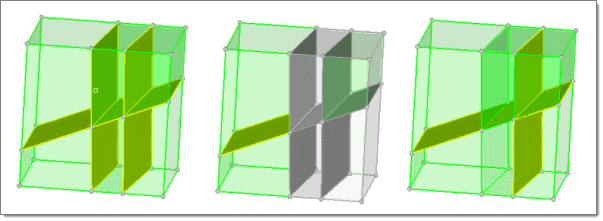
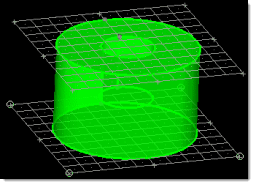
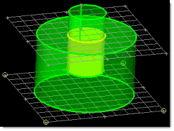
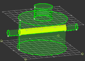
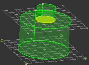
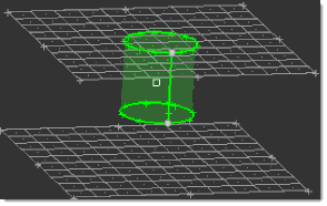
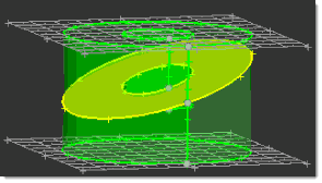
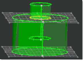
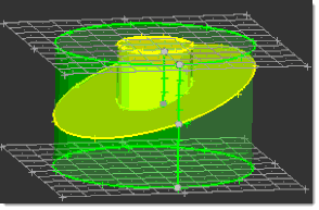
Use the Merge subpanel to join solid entities that are currently separated by a narrow gap.

You can use this feature to combine solids that are currently separated by a surface (shown in yellow).

Note:The intervening faces of the solids do not disappear completely; instead they become a single, shared face rather than two separate faces.

trimsolidwithsurf_4     trimsolidwithsurf_1

The dividing surface (yellow) becomes shared (green) after merging.

You can merge solids in two ways: either select solids to merge, or select intervening surfaces to remove.


Panel Inputs

Input

Action

to be merged: solids

Select the solids you wish to merge by picking them from your model, or by using the extended entity selection menu.

to be merged: remove scratches

If one or more faces of your model include scratches (surface features on the face which do not completely divide the face), activate the remove scratches checkbox to remove them during the merge process.

merge by removal: surfs

Select the surfaces you wish to remove by picking them from your model, or by using the extended entity selection menu.


Comments

This process uses the *solid_untrim command or the *solid_untrim command, as appropriate.


hmtoggle_arrow1Detach

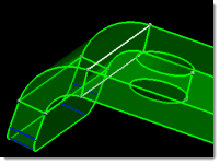
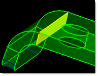
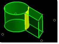
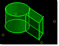
Use the Detach subpanel to detach (separate) selected a solid from neighboring solids with which it shares one or more common faces (drawn in yellow).

The shared/partition faces between the selected solids and the surrounding solids will be duplicated to become bounding faces of the separated solids. The partitioning faces within the selection will be maintained after they are detached from the rest of the model.

solid_edit_detatch1

From left to right this series shows 6 attached solids; selection of 4 of the solids; and the subsequently detached
solids. Notice that the selected solids weren’t detached from each other--only from the non-selected solids

The only input on this subpanel is a solids selector.  Use it to pick the solids that you wish to detach from each other.


hmtoggle_arrow1Boolean

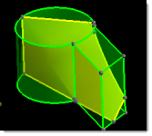
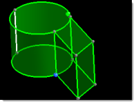
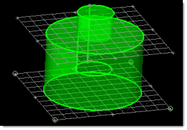
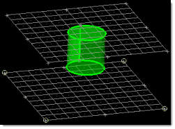
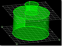
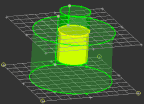
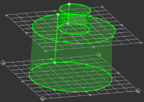
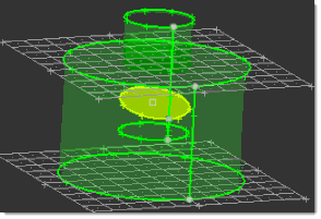
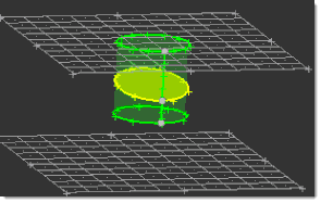
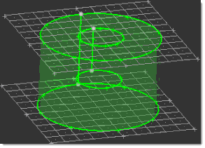
Use the Boolean subpanel to perform complex trimming and merging operations, such as trimming a pair of intersecting solids down to only the portions of them that coincide.

solidedit_boolean_start     solidedit_boolean_atimesb

In this example, only the portion shared by both cylinders is retained.

Simple vs. Advanced Boolean Operations

You can perform Boolean operations in a simple mode or advanced mode.  In both cases, the operation combines the solids according to your specifications.  However, the advanced mode also allows you to decide which internal intersection surfaces to keep.

Note:Each of the examples in this subpanel help use the same base model as the screenshots shown above: two cylinders, the smaller of which is partially buried within the larger one along a shared axis.  Whenever the help refers to solid groups A and B, the larger cylinder is group A while the smaller one is group B.  (The terms "group A" and "group B" are used because each group can contain more than one solid, even though the simplified illustrations used here contain only one solid per group.)


Panel Inputs

Input

Action

simple (combine all)

Activate this radio button to do a simple combination of solids.

advanced

Activate this radio button to do a complex boolean operation.  This causes the list of available operations to change, and reveals the combine through list of options.

A: solids

Pick one group of solids (usually the ones which you want to add to or subtract from).

B: solids

Pick the other group of solids (usually the ones that you wish to modify the ones in group A).

swap A and B

If you wish to invert the selection of A and B, activate this checkbox.

operation:

Choose the type of Boolean operation to perform:

union

This involves combining multiple solids into single solids.

solidedit_boolean_aplusb

intersection

This involves keeping only the coincident parts of a group of solids—that is, only the portions of each solid that occupy the same space.  The result is combined into a single solid, and everything that is not coincident is discarded.

solidedit_boolean_atimesb

removal

This operation involves removing coincident pieces of solids from other solids.  For example, a cylinder partially buried in another solid can be removed in such a way that it leaves a cylindrical recess in the other solid.

solidedit_boolean_aminusb

You can also remove common parts—similar to the intersection option, the operation concerns shared portions of solids.  However, instead of keeping the shared portions and deleting the rest, this option would remove the shared portions and retain the rest.

cuts

This operation is similar in some ways to removal of coincident parts, but it retains one of the solids.  Using the same example of a cylinder given for removal, the cut option would still create the cylindrical recess in the other solid—but would retain the cylinder, creating a cylindrical separating surface (shown in yellow) between the two solids.

solidedit_boolean_cutawithb


Advanced operations--except for A (keep A parts)--cannot be performed without using one of the combine through options.  Thus, specific examples of the end results are shown for combine through, below.

A+B (keep all parts)

The two solids combine into a single solid, with shared portions merged.

A*B (keep common parts)

The overlapping portions of the selected solids remain while the rest of each chosen solid is discarded.

A-B (del B parts)

The B solids are deleted and so are the portions of A that they share, leaving empty spaces in A where B used to intersect it.

A^B (del common parts)

The portions of A and B that occupy the same space are deleted, but retains any portions of each group that do not overlap.

A (keep A parts)

Everything except for the solids specified in group A is deleted.  Surfaces to indicate the original overlap with B are retained and highlighted, but nothing is removed from group A.


Using advanced operations also enables (and requires) the combine through options.

combine through:

The effects of these options depend on the operation performed, and not all options are available for every operation.  The possible options, and their outcomes, are shown in each expanding link below:

If you choose none, none of the intersection surfaces will be removed.

advbooleana_plus_b_none

Here, none of the intersection surfaces are discarded.

If you choose All internal faces, all of the surfaces inside the solids at their intersection will be removed.

advbooleana_plus_b_allinternal

Here, all of the intersection surfaces have been discarded.

If you choose All AB faces, only the surfaces that occur where the A and B groups touch will be removed. This means that other, pre-existing surfaces that pass through A and B will not be removed.

advbooleana_plus_b_allab

In this example, a third solid has already created internal surfaces through the area where A and B combine, but only the surfaces specific to the intersection of A and B are removed.

If you choose AB faces in B (B cuts A), the surfaces that lie inside of B and occur where A and B touch will be removed.

advbooleana_plus_b_abinb

Here, the intersection surfaces inside B are gone, but the external one remains.


Note:This setting only applies to pre-existing internal surfaces, not the intersection surfaces of the A and B groups:

advbooleanatimesb_start

If you choose none, none of the the intersection surfaces will be removed.

advbooleanatimesb_none

If you choose All internal faces, all of the surfaces inside the intersection of the solids will be removed.

advbooleanatimesb_all


Note:This setting only applies to pre-existing internal surfaces, not the intersection surfaces of the A and B groups:

advbooleana-b_start

If you choose none, none of the intersecting surfaces inside of A will be removed.

advbooleana-b_none

If you choose All internal faces, all of the surfaces inside the intersection of the solids will be removed.

advbooleana-b_allinternal


Note:This setting only applies to pre-existing internal surfaces, not the intersection surfaces of the A and B groups:

advbooleana-b_start

If you choose none, none of the internal surfaces will be removed.

advbooleana^b_none

If you choose all internal faces, all of the internal faces will be removed.

advbooleana^b_all


There are no combine through options for A (keep A parts).

Everything except for the solids specified in group A is deleted.  Surfaces to indicate the original overlap with B are retained and highlighted, but nothing is removed from group A.

advbooleana_keepa