BasicFEA

Distance panel

Distance panel

Previous topic Next topic Expand/collapse all hidden text  

Distance panel

Previous topic Next topic JavaScript is required for expanding text JavaScript is required for the print function  

Use the Distance panel to determine the distance between two nodes/points or the angle between three nodes/points, or to change distances or angles.


Panel Usage


The panel is split into multiple subpanels.  Switching between subpanels will not revert the settings, but in some cases your selections may be affected.  Each subpanel has selection criteria as well as distance displays which are populated as soon as points or nodes are selected.  However, the distance displays can also be manually changed to move the selected nodes or points.

distance_panel

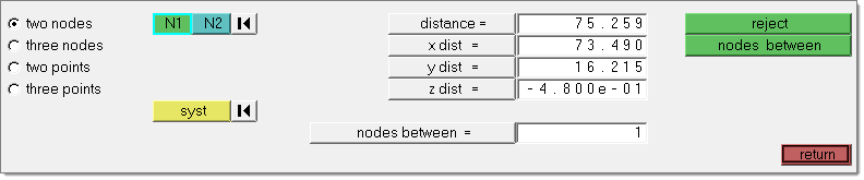
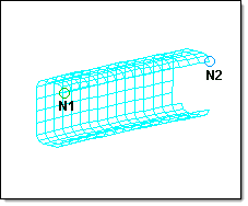
You can measure the distance between two nodes/points by specifying the two nodes/points; the total distance between the nodes/points, and the x, y, and z distances are displayed.

If you want to change the distance between two nodes/points, you can change the total distance, or any of the x, y, or z component values. The total distance will be recalculated if you have changed any of the x, y, or z component values.  After you have changed the desired values, BasicFEA follows the initial vector and relocates the second node/point at the specified distance along that vector.  The node selected as N1 will remain fixed, only the N2 node will be moved.

You can also determine the existing angle between three nodes/points.  After you have selected the three nodes/points, the value of the angle is displayed.

You can change the angle between three nodes/points (where three nodes/points, N1, N2, and N3 define a plane, with N2 as the center) by specifying the three nodes/points and supplying the desired angle.  After you have given the new value for the angle, BasicFEA moves N3 along the arc formed by swinging N3 around N2, until the angle is equal to the one you specified.

Any modifications of the node or point positions are always made in the global rectangular coordinate system, regardless of the measurement system used.


Examples


Distance between two nodes:

HM_Panels_bmp00087

The distance between nodes N1 and N2 is displayed in the distance = menu item as the total distance.  The distance is further broken down into the components and displayed in x dist =, y dist =, and z dist =.


Distance between three points:

distance_points

The distance between the points is displayed in the distance = menu item as the total distance.  The distance is further broken down into the components and displayed in x dist =, y dist =, and z dist =.


Angle between three nodes:

HM_Panels_bmp00088

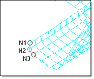
The angle between the nodes N1, N2, and N3 is displayed in the angle = field.


Angle between three points:

angle_points

The angle between the points is displayed in the angle = field.


Subpanels and Inputs


The Distance panel contains the following subpanels and command buttons:

expand-green-10Two Nodes

Use the Two Nodes subpanel to accept two nodes and an optional coordinate system as inputs, and then find the distances between them. Optionally, you can add a number of nodes between the selected nodes.


Panel Inputs

Input

Action

N1 / N2

The first and second nodes you wish to measure between.

syst

Allows you to specify the coordinate system within which to measure the distances and angles. The selected coordinate system affects the measured values only. If a non-rectangular coordinate system is selected, the meaning of the X,Y and Z component distances will change accordingly, although the field labels will not be changed.

distance

The total distance covered by the selected set of nodes or points.

x, y, z dist

The X, Y, and Z direction component distance between the selected nodes or points.

angle

The angle formed by the three nodes or points, using node/point 2 as the angle vertex such that a straight vector equals 180 degrees.

nodes between

Type in a number of nodes you wish to create, evenly spaced along the vector between the first and second selected nodes.


expand-green-10Three Nodes

Use the Three Nodes subpanel to accept three nodes and an optional coordinate system as inputs, and then find the distances and the angle between them. Optionally, you can add a number of nodes between the selected nodes.


Panel Inputs

Input

Action

N1 / N2 / N3

The first, second and third nodes you wish to measure between.

syst

Allows you to specify the coordinate system within which to measure the distances and angles. The selected coordinate system affects the measured values only. If a non-rectangular coordinate system is selected, the meaning of the X,Y and Z component distances will change accordingly, although the field labels will not be changed.

distance

The total distance covered by the selected set of nodes or points.

x, y, z dist

The X, Y, and Z direction component distance between the selected nodes or points.

angle

The angle formed by the three nodes or points, using node/point 2 as the angle vertex such that a straight vector equals 180 degrees.

radius

The radius of the circle going through the three selected nodes. This field is read-only; you cannot edit the value displayed.

nodes between

Type in a number of nodes you wish to create, evenly spaced along the vector between the first and second selected nodes.


expand-green-10Two Points

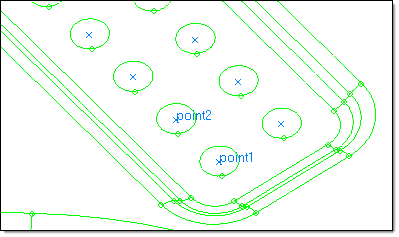
Use the Two Points subpanel to accept two points and an optional coordinate system as inputs, and then find the distances between them. Optionally, you can add a number of points between the selected ones.


Panel Inputs

Input

Action

point 1 / point 2

The first and second points you wish to measure between.

syst

Allows you to specify the coordinate system within which to measure the distances and angles. The selected coordinate system affects the measured values only. If a non-rectangular coordinate system is selected, the meaning of the X,Y and Z component distances will change accordingly, although the field labels will not be changed.

distance

The total distance covered by the selected set of nodes or points.

x, y, z dist

The X, Y, and Z direction component distance between the selected nodes or points.

angle

The angle formed by the three nodes or points, using node/point 2 as the angle vertex such that a straight vector equals 180 degrees.

points between

Type in a number of nodes you wish to create, evenly spaced along the vector between the first and second selected nodes.


expand-green-10Three Points

Use the Three Points subpanel to accept three points and an optional coordinate system as inputs, and then find the distances and the angles between them. Optionally, you can add a number of points between the selected ones.


Panel Inputs

Input

Action

point 1 / point 2 / point 3

The first, second and third points you wish to measure between.

syst

Allows you to specify the coordinate system within which to measure the distances and angles. The selected coordinate system affects the measured values only. If a non-rectangular coordinate system is selected, the meaning of the X,Y and Z component distances will change accordingly, although the field labels will not be changed.

distance

The total distance covered by the selected set of nodes or points.

x, y, z dist

The X, Y, and Z direction component distance between the selected nodes or points.

angle

The angle formed by the three nodes or points, using node/point 2 as the angle vertex such that a straight vector equals 180 degrees.

radius

The radius of the circle going through the three selected nodes.  This field is read-only; you cannot edit the value displayed.

points between

Type in a number of nodes you wish to create, evenly spaced along the vector between the first and second selected nodes.


hmtoggle_arrow1Command Buttons

The following action buttons appear throughout the subpanels:

Button

Action

reject

Reverts the most recent change made, whether in distance or points/nodes between.

nodes between

Click this to create the number of nodes specified by the nodes between = field between the selected nodes.

circle center

Uses the three selected nodes/points as input to create a best-fit circle and then generates a new visible node or point at the circle's center.

points between

Type in a number of points you wish to create, evenly spaced along the vector between the first and second selected points.

return

Exits the panel.