Creating the Model
Create the model in CADFEKO. Define any ports and sources required for the model. Specify the operating frequency or frequency range for the model.
-
Import the Parasolid geometry of the car from the file
car_geometry.x_b
Note: The model is included in the Feko installation.
-
Rename the three imported parts as follows:
- The structure for the car: car_body.
- The structure for the antenna: antenna.
- The structure for the windscreen: windscreen.
-
Union car_body and antenna.
Note: The windscreen curvature reference is not part of the union as it is not required to be electrically connected to the model.
- Add a wire port (vertex) on the wire that connects the antenna to the car body.
- Add a voltage source to the port. (1 V, 0°, 50 Ω).
-
Create a dielectric medium (glass).
- Relative permittivity: 7
- Dielectric loss tangent: 0.03
- Label: glass
-
Create a dielectric medium (PBV foil).
- Relative permittivity: 3
- Dielectric loss tangent: 0.05
- Label: pvb_foil
-
Create a layered dielectric.
- Label: windscreen_layers
-
Layer 1:
- Thickness: 2.1e-3
- Dielectric material: glass
-
Layer 2:
- Thickness: 0.76e-3
- Dielectric material: pvb_foil
-
Layer 3:
- Thickness: 2.1e-3
- Dielectric material: glass
-
Create a windscreen medium.
- Layer definition: windscreen_layers
- Offset L: 2.1e-3 + 0.76e-3
-
Label: Windscreen1
Tip: Variable Offset L specifies the reference plane where the windscreen antenna (wires) are located. For this example, the antenna is placed between the two layers, glass and pvb_foil.
-
Specify the windscreen curvature reference.
- Select the single face of the windscreen.
-
Include the windscreen curvature reference as part of the windscreen
solution.
Note: The windscreen curvature reference is used as part of the windscreen solution to define the shape and position of the windscreen.Tip: Open the Face properties dialog, click the Solution tab. From the Solve with special solution method list, select Windscreen.
A windscreen curvature reference is displayed semi-transparent in the colour of the windscreen definition. -
Specify the windscreen antenna (wires).
- Select the windscreen antenna wires.
-
Solve the windscreen antenna with the windscreen solution method.
Note: Variable Offset A is the distance from the windscreen curvature reference to the windscreen antenna (wires). For this example, set Offset A equal to 0 to place the antenna on the reference plane.Tip: Open the Edge properties dialog, click the Solution tab. From the Solve with special solution method list, select Windscreen.
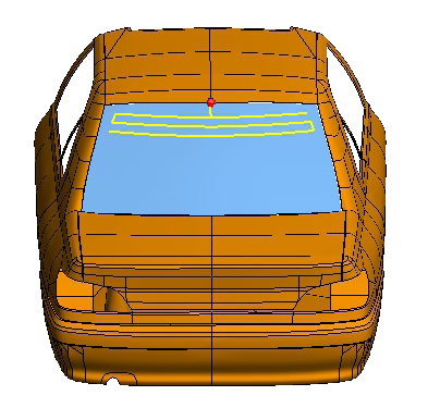
Figure 1. 3D view showing the selected windscreen antenna (indicated in yellow). - Set the continuous frequency range from 90 MHz to 110 MHz.