Block Category: Real Time
Through the Setup dialog box for the MCC Input block, you define the base address and channel number to which the pulse width modulated waveform is sent. You also use the Setup dialog box to set the clock frequency and to provide the PWM block with a unique name.
To specify MCC Input block properties
1. Choose Blocks > Real Time and drag an MCC Input block into the work area.
2. Choose Edit > Block Properties and click the MCC Input block, or right-click the MCC Input block.
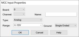
The MCC Input Properties dialog box appears.

3.
Do one or more of the following:
|
Use this parameter |
To |
|
Board # |
Select the installed Measurement Computing board. Text that describes the board will appear to the right. |
|
Channel |
Indicate the analog, digital, or counter channel. For each 8255 unit, channels 0 – 7 correspond to Port A; channels 8 – 15 correspond to Port B; channels 16 – 23 correspond to Port C. Note that multiple digital devices are treated like one large device. Thus, digital channel 24 corresponds to Port A bit 0 on the second 8255 digital device. |
|
Type |
Indicates whether the board is analog, digital, or counter channels. The channel count is adjusted to reflect the channel type. |
|
Name |
Provide a unique name for your MCC Input block. |
|
Range |
Indicate the voltage range for the I/O board. |
|
Ground |
Indicate whether the I/O board is single-ended (that is, single ground for all channels) or differential (that is, floating ground). If you choose differential, the channel count is adjusted to reflect the channel type. |
4. Click OK, or press ENTER.