Through the Setup dialog box for the PWM block, you define the base address and channel number to which the pulse width modulated waveform is sent. You also use the Setup dialog box to set the clock frequency and to provide the PWM block with a unique name.
To specify PWM block properties
1. Choose Blocks > Real Time and drag a PWM block into the work area.
2. Choose Edit > Block Properties and click the PWM block.
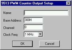
The 9513 PWM Counter Output Setup dialog box appears.
3.
Do one or more of the following:
|
Use this parameter |
To |
|
Name |
Provide a unique name for your PWM block. By naming PWM blocks, you reduce the risk of misreading your diagram, particularly when you are using more than one PWM block. |
|
Base Address |
Indicate the I/O port register address through which the real-time driver commands the board. Enter the base address as a hexadecimal number, followed by an optional “H.” |
|
Channel |
Enter a number that corresponds with the channel number on the screw terminal or termination panel supplied with your I/O board. Embed uses channel 0 as the first channel, even if the documentation supplied by the board vendor describes the first channel as channel 1. |
|
Clock Freq. |
Enter a value that corresponds with the base frequency crystal value set on your I/O board. If the value you enter does not match the base frequency crystal value, erroneous results are produced. |
4. Click OK, or press ENTER.