The frequency block measures a signal on an I/O board at the specified base address and channel number and outputs the frequency in hertz.
To specify frequency block properties
1. Choose Blocks > Real Time and drag a frequency block into the work area.
2. Choose Edit > Block Properties and click the frequency block, or right-click the frequency block.
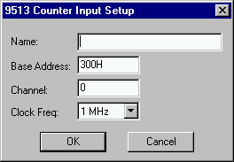
The 9513 Counter Input Setup dialog box appears.
3.
Do one or more of the following:
|
Use this parameter |
To |
|
Name |
Provide a unique name for your frequency block. By naming frequency blocks, you reduce the risk of misreading your diagram, particularly when you are using more than one frequency block. |
|
Base Address |
Indicate the I/O port register address through which the real-time driver commands the board. Enter the base address as a hexadecimal number, followed by an “H.” |
|
Channel |
Enter a number that corresponds with the channel number on the screw terminal or termination panel supplied with your I/O board. Embed uses channel 0 as the first channel, even if the documentation supplied by the board vendor describes the first channel as channel 1. |
|
Clock Freq. |
Enter a value that corresponds with the base frequency crystal value set on your I/O board. If the value you enter does not match the base frequency crystal value, erroneous results are produced. |
4. Click OK, or press ENTER.