Block Category: Real Time
The CAN PEAK write block writes data to the CAN bus. The top “Tx” pin must have the value 1 for the block to send a CAN packet. The remaining pins are data pins. The values presented on the data pins are stored into the 8-byte CAN packet buffer for transmission according to the data type and byte offset as setup in the CAN Transmit Properties dialog box.
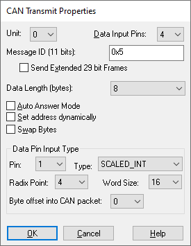
Auto Answer Mode: Writes data only when a device requests it.
Data Input Pins: Specifies the number of output pins on the CAN PEAK write block. Each pin refers to a data item within the 8-byte CAN packet. Note that the packet length can be from 0 to 8 bytes.
Data Length: Specifies the number of bytes in the data packet. It can between 0 and 8 bytes.
Each input data pin corresponds to a data item within the 8-byte data packet of a CAN message. For each pin, you can choose:
Byte Offset into CAN Packet: Selects the byte offset into the 8-byte CAN data packet.
Radix Point: Selects the radix point for Scaled Int data types.
Type: Selects the data type for the pin.
Word Length: Selects the word length for Scaled Int data types.
Message ID: Specifies the CAN message identifier. This can be from 0 to 0x7FF for 11 bit identifiers, or from 0 to 0x1FFFFFFF for extended 29-bit identifiers.
Send Extended 29 Bit Frames: The default is 11 bit identifiers. Checking this box will result in the use of 29 bit identifiers.
Set Address Dynamically: Adds a second pin named addr. This pin provides the CAN address for the transmit destination. This value can be changed on the fly as the diagram is executed.
Swap Bytes: Causes the 8-byte data packet to be byte swapped on a 2-byte word basis.