
Block Category: Animation
Description: The animate block lets you animate an image during simulation.
Animation occurs only when you initiate a simulation with display mode active. In this mode, all wires are hidden, all blocks are frozen in place, and except for the interactive elements on button and slider blocks, block parameter values cannot be changed.
Input signals: Animation works by feeding signals into an animation block. The signals drive the coordinates of the animation block, which result in motion.
The animate block accepts five input signals.
Signal fed into the top input: The top input connector tab determines which image is applied to the animate block. An input signal value of 0 causes the bitmap image file corresponding to state 0 to be displayed; an input signal value of 1 causes the bitmap image file corresponding to state 1 to be displayed; and so on. Signal values entering the top input adhere to these rules:
When a signal value is a non-integer, the animate block truncates it to integer form.
When a signal value is greater than the number of set states, the animate block uses the highest set state.
When the signal value is negative, the animate block uses state 0.
Signals fed into the x, y, w, and h inputs: The “x” and “y” connectors provide the x,y screen position coordinates for the image. The input connector tabs labeled “w” and “h” provide the width and height of the image. By varying these values, you can create movement and depth.
The values fed into the x, y, w, and h inputs represent display pixels. The x, y position 0,0 is the upper left corner of the Embed window. Positive values extend to the right and down. For your image to appear on most video screens, keep its position within the bounds of a VGA screen (640x480).
You must perform all coordinate conversion manually.
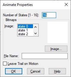
File Name: Indicates the name of the BMP file to be applied to the selected state. You can enter the complete path of the BMP file, or click Image to locate and select a BMP file.
Image: Indicates the state to which a BMP file is to be applied.
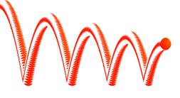
Leave Trail on Motion: Leaves a trail of the BMP image as the simulation progresses.
Number of States: Indicates the number of images to be applied to the block. The limit is 16.
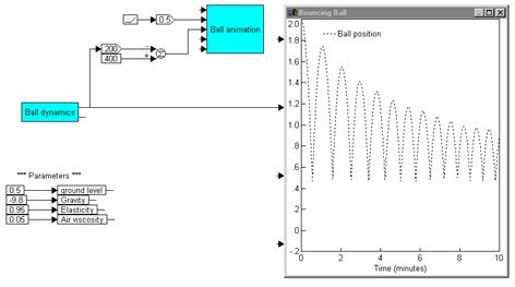
Consider the bouncing ball animation shown below:
The ball is represented as a single animate block. Movement is introduced by changing the ball’s x,y screen position coordinates. As the simulation progresses, the signals entering the animate block continually update its position. The diagram below drives the simulation of the bouncing ball.
To create the illusion of depth, you can vary the ball’s w,h size coordinates.
The values fed into the x, y, w, and h inputs represent display pixels. The x, y position 0,0 is the upper left corner of the Embed window. Positive values extend to the right and down. For your image to appear on most video screens, keep its position within the bounds of a VGA screen (640x480).
You must perform all coordinate conversion manually. For example, the equations that determine the position of a bouncing ball are shown below:
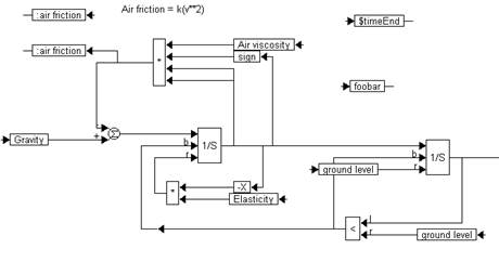
However, before the output of the resetIntegrator block can be fed into the animate block, the position of the ball must be mapped to screen coordinates, as shown below:
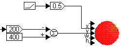
The objective is to animate the bouncing of the ball as a function of time. This means that time is the independent variable, or the x-axis. A ramp block is used to generate time, which ranges between 0 and 1000. A gain of 0.5 is used to scale time so that the amount of space used on the screen in the horizontal direction is limited in the range 0 to 500 pixels.
The ball position, y, varies from 0.5 to 2 in the simulation. This is scaled 0 to 300 pixels by using the scaling shown. Note that the pixel location (0,0) corresponds to the top left corner of your screen, and the largest pixel location is the bottom right