Model: Machine Tool
Location: Examples > eMotor > Tutorials
The typical machine tool lathe is operated from a single-speed motor drive, together with multiple gear selection to vary chuck speed. Here a simpler design is considered: one with a single 10:1 gear reducer and a variable speed control drive for a 3-phase AC induction motor.
The lathe is required to operate with the following specifications:
Maximum work piece load: 1 meter by 0.1 meter diameter aluminum bar stock
Chuck speed control range: 30 to 400 RPM
Speed control accuracy: ± 5 RPM from set point steady state
Maximum load torque: not to exceed 0.3 N-m, introduced by cutting tool
The motor specifications are given as:
|
Motor parameter |
Value |
Units |
|
Stator resistance (per phase) |
9.4 |
Ohms |
|
Stator self inductance (per phase) |
0.402 |
Henries |
|
Stator leakage inductance |
0.032 |
Henries |
|
Rotor resistance |
7.1 |
Ohms |
|
Rotor leakage inductance |
0.032 |
Henries |
|
Number of poles |
2 |
|
|
Rotor inertia |
0.001 |
Kg-m2 |
|
Rotor viscous damping constant |
0.0001 |
Kg-m2 - s |
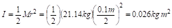
The moment of inertia of the chuck and moving drive assembly is given as 0.1 kg-m2. The moment of inertia of the work piece is calculated as:

Since the axes of the chuck and work piece are coincident, they add to total 0.126 kg m2.
One very effective way of controlling speed by an induction motor is to control the stator field frequency. Since stator flux is inversely proportional to frequency below the base frequency, it is necessary to adjust voltage proportional to frequency to maintain constant flux. For frequency above the base frequency (power supply limitation), the voltage is kept constant. This method is the basis of the design, with one minor improvement. The constant volts to frequency control mentioned above are used as a feed forward leg of a feed forward – proportional integral controller (PI). The PI component of the control is used to adjust any error that may occur due to motor slip and loading from the cutting tool. Motor speed is estimated from motor shaft position measured by an incremental encoder. To drive the motor, an inverter is used with six-step logic to switch polyphase-rectified voltage producing a balanced 3-phase signal.