A sample diagram — WebTest05 — with a Web Server block is included under Examples > Embedded > CortexM3 > Webserver.
As you can see, from the diagram standpoint, the Web Server block is treated like any other block in the Embed diagram. It takes input values and supplies output values. The Web Server block operates asynchronously. In other words, it posts its input data to the page but does not wait for a response. The output data it provides on the output pins are whatever is in the local buffer from the last asynchronous data received from the page.
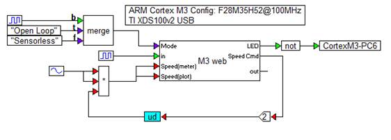
In the sample diagram above, connectors are color coded to data type:
Green: integer
Purple: string
Red: floating point
The diagram generates some simple data merely to exercise the control on the web page.
The Mode input is a string that updates dynamically. The “in” input is an edit display that will show the integer numeric value of the square wave input. The Speed (meter) input is identical to the Speed (plot) input and is a sin squared to produce a value varying between zero and one scaled by the Speed Cmd slider output and a gain of two. The LED output is a check box with value zero or one. This is connected to GPIO PC6 which is wired to an LED on the Texas Instruments Control card. This lets you turn the LED on and off from the web page. The “out” pin represents the floating-point value entered into the Out control on the web page. It is not used in this sample diagram.
When you compile the diagram, the web page below is automatically generated. Using the web page, you can observe and control your application on the target board.
