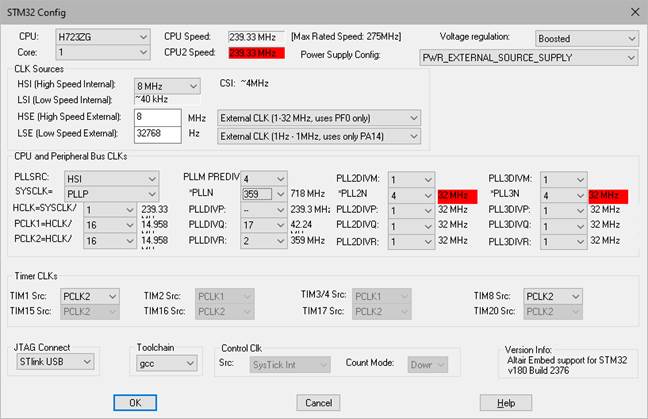
The STM32 Config lets you configure the settings for the STM32. After you enter the settings, an STM32 Config block is inserted into the diagram. Note that
HSE: Chooses the speed of the external clock/crystal. Select the HSE mode (clock, crystal, or unused) in the dropdown to the right.
HSI: Indicates the speed of the HSI clock.
LSE: Chooses the speed of the external clock/crystal. Select the LSE mode (clock, crystal, or unused) in the dropdown to the right.
LSI: Indicates the speed of the LSI clock.
MSI: Indicates the speed of the MSI clock.
Count Mode: Displays the count mode. This is a read-only parameter.
Src: Displays the periodic sampling interrupt source for the main control loop in Embed. This is a read-only parameter.
Core: Selects the core device. Only available on STM32 dual core MCUs (H723VE – H735ZG targets).
CPU: For some targets, there is a family of CPU types. It is important to select the exact CPU type for the specified target.
CPU Speed: Indicates the speed and the maximum rated speed of the CPU. This parameter is affected by the Voltage Regulation parameter. STM32 H723VE – H735ZG targets are dual core. There is a CPU2 Speed parameter for the second core.
HCLK=SYSCLK/: Selects the divider for the HCLK.
HSE_PREDIV: Divides the HSE source. It can be divided by 2 – 16. This parameter is available for only F3 series targets that do not end in D or E.
PCLK1=HCLK/: Selects the divider for the PCLK1. Used by the APB1 peripherals.
PCLK2=HCLK/: Selects the divider for the PCLK2. Used by the APB2 peripherals.
PLLM PREDIV / and *PLLN: PLLM PREDIV divides the PLL source. It can be divided by 1 – 16. *PLLN multiples the results. If PLLN is highlighted in red, the value is either too high or too low. This parameter is available for all targets except F3 series that do not end in D or E.
PLL2DIVM and *PLLN2: PLL2DIVM divides the PLL source. It can be divided by 1 – 16. *PLLN2 multiples the results. If PLLN2 is highlighted in red, the value is either too high or too low.This parameter is available for all targets except F3 series that do not end in D or E.
PLL3DIVM and *PLLN3: PLL3DIVM divides the PLL source. It can be divided by 1 – 16. *PLLN3 multiples the results. If PLLN3 is highlighted in red, the value is either too high or too low. This parameter is available for all targets except F3 series that do not end in D or E.
PLLDIVP, PLLDIVQ, PLLDIVR: Specifies the divider values for PLL outputs P, Q, and R. Only available on STM32 F4x, G0x, G4x, and L4x targets.
PLL2DIVP, PLL2DIVQ, PLL2DIVR: Specifies the divider values for PLL2 outputs P, Q, and R. Only available on STM32 F4x, G0x, G4x, and L4x targets.
PLL3DIVP, PLL3DIVQ, PLL3DIVR: Specifies the divider values for PLL3 outputs P, Q, and R. Only available on STM32 F4x, G0x, G4x, and L4x targets.
PLLSRC: Selects the clock source used to drive the PLL input. You can also choose the PLL multiplier and divisor.
SYSCLK: Chooses the input for the system clock.
JTAG Connect: Indicates the JTAG driver to be used for HotLink communication.
Power Supply Config: Configures the power supply. Only available onSTM32 F103x and H7x targets.
TIM1 Src – TIM20 Src: Chooses between the PCLK and the PLLCLK * 2 for each timer. TIM1 is available for all STM32F3x devices; remaining timers are selectable only on the STM32F3nnxD/E parts.
Toolchain: Selects the compiler to use.
Voltage Regulation: Controls the internal voltage of the chip. The lower the level, the less power the chip uses. When you change the Voltage Regulation, the CPU Max Rated Speed is changed accordingly.