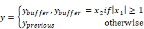
The unitDelay block specifies a clocked unit delay. The input connector tabs are marked b (for Boolean clock) and x (for main signal). When the Boolean clock does not equal zero, the value contained in the single element buffer is copied to the block output (where it holds this value until the next non-zero Boolean clock). The current value of the main signal is stored in the unit buffer.
The unitDelay block is intended for modeling a digital delay in a continuous simulation. A typical digital delay is modeled by wiring a pulseTrain block to the Boolean input connector tab of the unitDelay block. Use the timeDelay block to model a continuous delay.
You can set the initial conditions for unitDelay blocks with variables. You can also reset unitDelay blocks to zeros using the System > Reset States command.
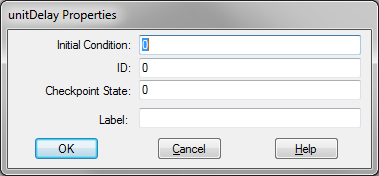
Checkpoint State: Contains the value of the unit delay at the checkpoint. If you have not checkpointed your simulation via the System > System Properties command, the value is zero.
ID: Reserved for future use.
Initial Condition: Sets an initial value for the output signal. The default is zero.
Label: Indicates a user-defined block label.
1. Clocking the unitDelay block
If you are working with unitDelay blocks, it is good programming practice to create a clock signal that you can use in every simulation. A typical clock signal can be generated as shown below.
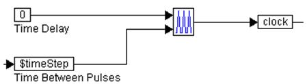
Here, a pulseTrain block is assigned two external inputs:
•The top input is the time delay for the pulseTrain block. The time delay value for the pulseTrain block is the amount of time the pulseTrain block waits before producing pulses. This time delay value must not be confused with the amount of time delay generated by the unitDelay block.
•The bottom input is the time between pulses.
The output of the pulseTrain block is fed to the variable clock. This variable can be used anywhere in the simulation to clock unitDelay blocks.
2. Introduction of a one-step delay
For a given signal, a one-step delay can be introduced as:
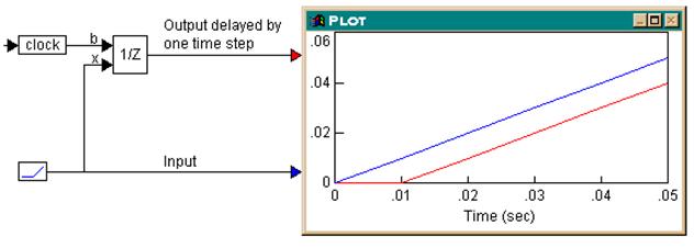
During simulation, the actual and delayed signals are plotted in the plot block. The output of the unitDelay block is delayed by one step (equal to 0.01 in this case) as compared to the input.
3. Using a multi-step delay with cascaded unitDelay blocks
To achieve multi-step delays, unitDelay blocks that implement one-step delays, can be cascaded. Consider the example where a three-step delay is introduced.
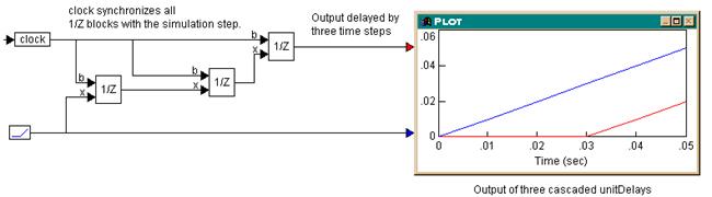
Three unitDelay blocks, all clocked at the simulation step, are cascaded. Since each unitDelay introduces a one-step delay between its input and output, the output of the third unitDelay block is delayed by three steps compared to the input. The plot block shows this behavior, with a simulation step size of 0.01.