Embedded Category: C2407, F280x
Block Category: TI 16-bit DMC, TI 32-bit DMC
Operating Mode Availability
•Simulation mode: NO
•C code generation mode: YES
The Space Vector PWM block computes a timer period value based on the CPU frequency and the value entered for the Carrier Frequency in the Space Vector PWM Properties dialog box. For example, a carrier frequency setting of 30kHz for a 30MHz CPU yields a timer period of 1000.
The top three inputs (a, b, and c) dynamically determine the duty cycle of each of the six PWM outputs by assigning the proper fraction of the timer period to the compare register. An input value on pin a, b, or c of –1 gives 0% duty cycle; an input value of 0.99999996 gives 100% duty cycle and the PWM varies linearly in between. If 0.5 is supplied to the first input, the compare register would receive 750. The signal on PWM1 would be ON for 750 CPU clock ticks and OFF for 250 CPU clock ticks. If zero is supplied to the first input, the compare register would receive 500. The signal on PWM1 would be ON for 500 CPU clock ticks and OFF for 500 CPU clock ticks.
PWM outputs 2, 4, and 6 are the inverse of PWM outputs 1, 3, and 5, respectively.
The fourth block input (period) is intended for dynamically modulating the carrier frequency. An input value of 0.8 reduces the period by a factor of 0.8%. Thus, the carrier frequency increases by 25% (1/.8).
The Space Vector PWM block performs the following actions:
•Symmetrical pulse-width modulation (PWM) is used to control the inverter with GP timer 1 as PWM time base.
•PWM outputs 1, 3, and 5 control the turn-on and turn-off of the upper power devices.
•PWM outputs 2, 4, and 6 control the turn-on and turn-off of the lower power devices.
•The analog inputs are the amplified and filtered voltage outputs of resistors placed between the sources or emitters of low-side power devices and low-side DC rail.
This also allows PWM period modulation.
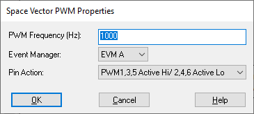
Event Manager: For the 2407, you can select EVM B, which is hardwired to the GP timer 3.
Pin Action: Indicates Active Hi or Low. If pin 1 is active high, the deadband unit will cause pin 2 to delay switching high for the deadband interval when pin 1 switches to low. If pin 1 is active low, the deadband unit will cause pin 2 to delay switching low for the deadband interval when pin 1 switches to high.
PWM Frequency: Indicates the base modulation frequency of the PWM. Note that this block is hardwired to GP timer 1 and drives pins PWM 1 - 6.