Target Category: STM32
Target Sub-Category: PWM
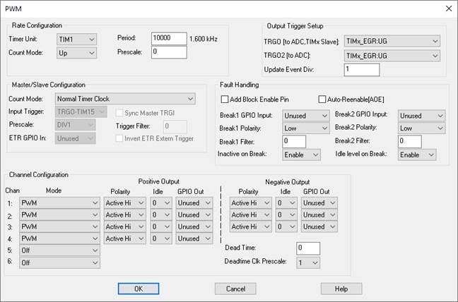
Channel 1-6: Specifies the channel to be configured. Each channel is associated with a compare register that is used to create PWM waveforms.
Dead Time: Sets the amount of deadband between PWM switching to avoid drawing too much current in a power-controlled circuit.
Deadtime Clk Prescale: Specifies the clock divisor for the deadtime. The divisor divides the timer clock to obtain a deadtime clock. For more information, see the STMicroelectronics documentation for the device you are using.
Mode: Determines the action on compare register match. There are a number of modes from which to choose. Normally, PWM mode is selected. For more information, see the STMicroelectronics documentation for the device you are using.
Negative Output: Only channels 1 – 3 have negative output.
•Idle: Specifies the output state on an occurrence of a break fault. Idle level on Break must be enabled. For more information, see TIMx OSSI bit in the STMicroelectronics documentation for the device you are using.
•GPIO Out: Specifies the output pin on the chip for the given signal.
Positive Output: Only channels 1 – 4 have positive output.
•Polarity: Determines if the active mode is High or Low. For more information, see the STMicroelectronics documentation for the device you are using.
•Idle: Specifies the output state on an occurrence of a break fault. Idle level on Break must be enabled. For more information, see TIMx OSSI bit in the STMicroelectronics documentation for the device you are using.
•GPIO Out: Specifies the output pin on the chip for the given signal.
Timers can have zero, one, or two break units.
Add Block Enable Pin: Uses hardware faulting mechanism. When you activate Add Block Enable Pin, you invoke breaking to perform analysis.
Auto-Reenable (AOE): Clears the break at the end of the PWM waveform.
Break1 GPIO In: Specifies the pin that will be used to invoke the break fault.
Break1 Polarity: Specifies the polarity of the break input signal.
Break1 Filter: Specifies the duration of the break input signal before the faulting is invoked.
Break2 GPIO In: Specifies the pin that will be used to invoke the break fault.
Break2 Polarity: Specifies the polarity of the break input signal.
Break2 Filter: Specifies the duration of the break input signal before the faulting is invoked.
Inactive on Break: When enabled and a fault occurs, each output line will be set to the inactive level (that is, the opposite of the active level). When neither Inactive on Break nor Idle Level on Break is enabled, the GPIO outputs go into a Hi-impedance state.
Idle Level on Break: When enabled and a fault occurs, each output line will be set to the idle level as specified per channel under Positive Output and Negative Output. When neither Inactive on Break nor Idle Level on Break is enabled, the GPIO outputs go into a Hi-Z state.
Count Mode: Selects the counter behavior. For more information, see the STMicroelectronics documentation for the device you are using.
ETR GPIO In: For external trigger connected to a GPIO pin of the device.
Input Trigger: Selects the source of the input trigger.
Invert ETR Extern Trigger: Inverts the ETR GPIO In trigger.
Prescale: Divides the rate of the input trigger.
Sync Master TRGI: You must select a TRGI mode under Count Mode. For more information, see the STMicroelectronics documentation for the device you are using.
Trigger Filter: Specifies the duration of the trigger signal before the trigger event is asserted.
TRGO (to ADC, Timx, Slave): Used by the ADC to start a conversion sequence. It can also be used by another timer as a trigger input.
TRGO2 (to ADC): Used by the ADC to start a conversion sequence.
Update Event Div: Divisor for the update event used to send update event triggers. For example, if you enter 1, the trigger is sent out for every update event; if 2 it sends out every other update event, and so on. An update event occurs when you get a counter overflow or underflow. For more information, see the STMicroelectronics documentation for the device you are using.
Count Mode: Determines the counting mode. For more information, see the STMicroelectronics documentation for the device you are using.
Period: Specifies the duration of a PWM waveform in units of timer ticks. In conjunction with the system clock selected for the timer, the timer Prescale and Count Mode, determines the frequency of the PWM waveform. For example, if the base clock rate is 72MHz and Prescale is 720 and the Count Mode is Up/Down (divide by 2), the effective clock rate is 50kHz. The frequency appears to the right of the Period. For more information, see the STMicroelectronics documentation for the device you are using.
Prescale: Scales the timer source to a slower rate. Can be any value between one and 65,536. For more information, see the STMicroelectronics documentation for the device you are using.
Timer Unit: Specifies the timer source.