Target Category: Linux Raspberry Pi
Target Sub-Category: PWM
Description: There are two independent output bit-streams, clocked at a fixed frequency, for the PWM block. Additionally, there are two independent PWM channels (0 and 1), each of which can be connected to a limited subset of GPIO pins. Both PWM channels are driven by the same PWM clock, whose clock divider can be varied. Each channel can be separately enabled. The average output of a PWM channel is determined by the ratio of DATA/RANGE for that channel.
The PWM pin available on the GPIO header is shared with the audio system. This means that you cannot use PWM output and play audio through the 3.5mm jack at the same time.
The PWM block accepts scaled integer (fixed point) 1.16 input.
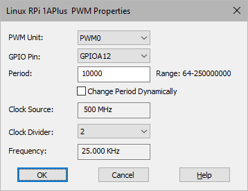
Change Period Dynamically: Produces an external input pin that lets you specify a fractional value for the period on-the-fly. The external value will be multiplied by the period and assigned to the period register. This allows you to dynamically modulate the PWM-based frequency.
Clock Divider: Specifies the value used to divide the system clock frequency that drives the PWM counter.
Clock Source: Indicates the PWM input clock speed. For Raspberry Pi, this is the system clock, which is determined by the CPU selected in the Target Config block.
Frequency: Indicates the frequency of the generated PWM signal.
GPIO Pin: Specifies the GPIO pin on the device. Click here for Raspberry Pi pin mapping.
Period: Specifies the number of PWM clock ticks for one complete PWM waveform. The frequency of the PWM signal is determined as follows:
Clock-Source-Frequency/Period = PWM-Frequency
For example, 150MHz/150 = 1MHz.
PWM Unit: Specifies the unit to be configured.