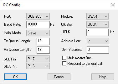
The I2C Config lets you configure the I2C unit.
Address Len: Specifies the length of the bus address. It can be either 7- or 10-bit.
Baud Rate: Indicates the base clock rate for master mode.
Selects the clock for the I2C unit. You have these choices:
ACLK: Auxiliary clock
Port: Selects the Comm
port
SMCLK: Submain clock
UCLK: External
clock
Initial Mode: Specifies the mode at boot time.
Module: Choose among USART, USCIB (new school), and USI (minimalist).
Multi-Master Bus: Set to TRUE if addressing is used.
Mux Pin: Selects which pin a given function is on.
Certain MSP430 devices have different functions for the same physical pin on the chip. This is because pins are expensive. Sharing time or space is called multiplexing, or muxing, for short. Because multiple functions compete for a given pin, you must choose what function a pin has. For flexibility, in some cases Texas Instruments has provided multiple possible pins for a given function. For instance, the CANTXB function can be on pin 8, 12, or 16. Pin 8 is shared with ePWM5A and ADCSOCA0, pin 12 is shared with TZ1 and SPISIMOB, pin16 is shared with SPISIMOA and TZ5. So, if you want ePWM5A on a pin, then you cannot use pin 8 for CANTXB, but rather you must use pin 12 or 16 instead.
Own Address: Indicates the address of this unit on the I2C bus. This is important in slave mode: messages that do not match Own Address will be discarded.
Port: Specifies the port.
Respond to General Call: Responds to address 0.
Rx Queue Length: Specifies the length of the receive queue.
SCL Pin/SDA Pin: Specifies mux pins for the I2C clock and data lines.
Tx Queue Length: Specifies the length of the transmit queue.
UCLK: Specifies the external hardware clock rate.