
This example describes how to use the Adafruit SSD1306 driver along with the Adafruit GFX general-purpose graphics software to print “Hello, world!” on the SSD1306 on an Arduino Uno coupled with a 128x32-bit display connected via I2C. You can easily modify the steps for a 64-bit display or SPI connection.
1. Attach the SSD1306 OLED to the Arduino Uno board as shown below. For wiring instructions, go to https://learn.adafruit.com/monochrome-oled-breakouts/wiring-128x32-spi-oled-display.
2. Start the Arduino IDE.
3. Click Sketch > Include Library > Manage Libraries and do the following:
a. In the Search box, enter ssd1306.

b. Under Adafruit SSD1306, select the most recent version and click Install.
c. Repeat steps a - b but this time search for and install the most recent version of Adafruit GFX library.

4. Click on File > Open > Examples > ssd1306_128x32_i2c and select ssd1306_128x32_i2c.ino.
5. To verify that the library modules have been installed correctly, compile the code from the Arduino IDE by clicking on the checkmark in the upper left corner of the Arduino window.
6. To verify that the hardware is connected properly and works as expected, click the right arrow in the upper left corner of the Arduino window to upload and run the code on your Arduino.
7. Start Embed and position it next to the Arduino window.

8. Create a new diagram and save it as OLED2.vsm.
9. Insert the following blocks into your diagram:
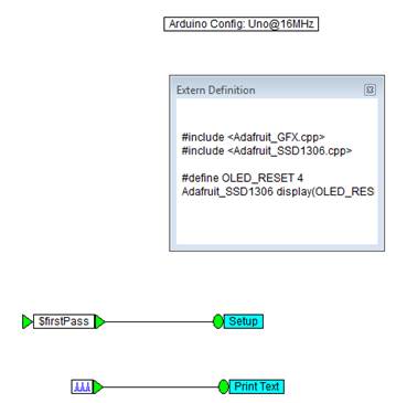
•Embedded > Arduino > Arduino Config block. Make sure it is configured for an Uno and the Comm port is set correctly.
•Embedded > Arduino > Extern > Extern Definition block in your diagram.
10. Right-click the Extern Definition block to access its Properties dialog box.
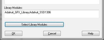
11. Click Select Library Modules.
12. In the External Library Selection dialog box, select Adafruit_SSD1306 and Adafruit_GFX_Library, then click OK..
13. The Extern Definition dialog box displays the selected libraries under Library Modules.
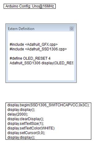
14. With the Arduino window and Embed window side-by-side, copy the #include, #define, and instantiation declarations from the Arduino example sketch and into the External Definition window.

15. In the Extern Definition window, rename the Adafruit_GFX.h and Adafruit_SSD1306.h to Adafruit_GFX.cpp and Adafruit_SSD1306.cpp. The CPP files contain all the driver logic.
16. Click OK.
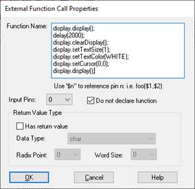
17. Integrate a setup loop into the diagram using the Extern Function block.
a. Insert an Extern Function block into the diagram beneath the Extern Definition block.
b. In the Arduino example sketch, copy the following statements into the Extern Function block under Function Name.
•display.begin(SSD1306_SWITCHCAPVCC, 0x3C).
•display.display();.
•delay(2000);.
•display.clearDisplay();
•display.setTextSize(1);
•display.setTextColor(WHITE);
•display.setCursor(0,0);
•display.display();
Your diagram will look like this:
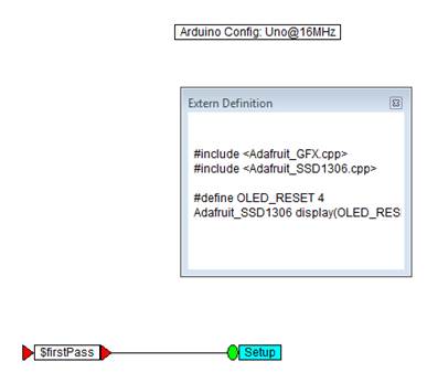
c. Encapsulate the Extern Function block in a compound block and name it Setup.
d. CTRL-right-click over Setup and in the dialog box, activate Enable Execution and click OK.

e. Wire a variable block into Setup and set the variable block to $firstPass. Because Setup runs only once at boot, the $firstPass flag is used to control the enabled compound to run once at boot.
18. Add one more Extern Function block to the top level of your diagram.
19. In the Arduino example sketch, copy the following statements into the Extern Function block under Function Name.
•Display.println(“Hello, world!”);
•display.display();
20. Encapsulate the Extern Function block in a compound block and name it Print Text.
21. CTRL-right-click over Print Text and in the dialog box, activate Enable Execution and click OK.
22. Wire a pulseTrain block into Print Text and set the Time Delay to 2s and the Time Between Pulses to 1. The pulseTrain block sets the frequency at which to print Hello, world!.
Your diagram will look like this:
23. Compile and download the library code to the Arduino.
24. Click Tools > Code Gen.
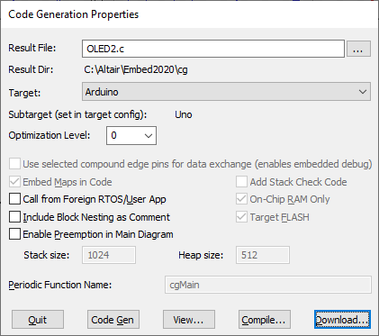
25. In the Code Generation Properties dialog box, click Compile.
26. The code is compiled in a DOS window. When the compilation completes, click Download.
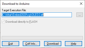
27. In the Download to Arduino dialog box, click Download to download the code to the Arduino and print Hello, world! on the SSD1306 display.
