Target Category: STM32
Description: The DAC block performs digital to analog voltage conversions.
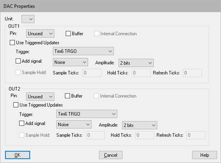
Unit: Specifies the DAC to be controlled.
Pin: Specifies the metal pin on the STM32 device. You have these options:
•Buffer: When driving the metal pin, you can buffer the signal, which means the chip is supplying more power.
•Internal Connection: Lets you use the voltage internally for a comparator.
Use Trigger Updates: Activate this parameter to use a trigger to control when Embed updates the value on the pin.
Trigger: Specifies the signal that will trigger a conversion.
Add Signal: Lets you add noise or a triangular wave signal to the base DC value. This is a common technique for some digital power control conversions.
Amplitude: Specifies how many bits of noise or triangular wave to add to the signal.
Sample Hold: Performs a sample and hold operation on the signal. This is a power conservation feature available on low-power devices. You control the sample and hold in the following ways:
•Sample Ticks: Specifies the number of ticks to sample the initial signal.
•Hold Ticks: Specifies the number of ticks to hold the signal before a refresh.
•Refresh Ticks: Specifies the number of ticks from digital to analog. Typically, the value is much smaller than the initial Sample Tick value.