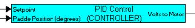
The controller has two inputs (desired and actual angles) and one output (voltage) to be applied to the motor.
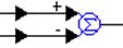
To begin modeling the controller, wire two wirePositioners to the inputs of a summingJunction block, and negate the second input, as shown below.
For ease of implementation, these blocks are encapsulated in a compound block called PID Control (CONTROLLER) and the inputs and outputs are labeled appropriately.
Inside PID Control (CONTROLLER), the output of the summingJunction is passed through a gain of 0.001 and fed as the error input for computing P (proportional), I (integral), and D (derivative) components of the controller. The proportional term, encapsulated in a compound block named proportional term is implemented as:
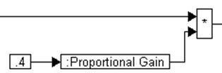
The proportional gain is set to 0.4.
The integral term, encapsulated in a compound block named integral term is implemented as:
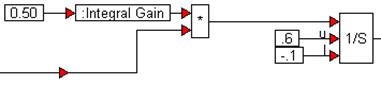
The integration is performed using a limitedIntegrator to prevent windup. The upper and lower limits are set to 0.6 and –0.1 respectively, and the integral gain is set to 0.50.
The derivative term, encapsulated as a compound block named derivative term is implemented as:
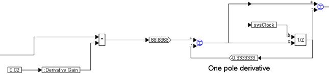
The computation of the derivative is implemented using a unitDelay block, two gain blocks, and two summingJunctions blocks, as shown above. The sysClock clock input to the unitDelay is defined using a pulseTrain block, and the contributions of the P, I, and D terms are summed up, as shown below.
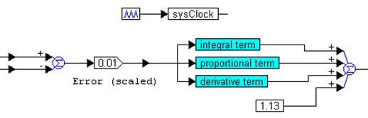
Because the motor needs a minimum of 1.13V to turn, a constant bias of 1.13V is added to the mix. To ensure that the voltage applied to the motor is within the rated voltage range, and to shut the motor down when the simulation run is complete, the limit and merge blocks are used, as shown below.
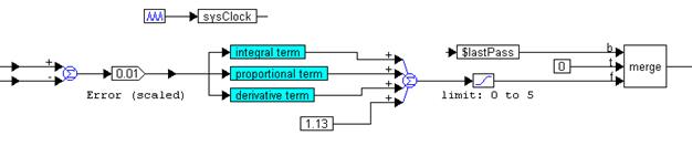
The output of the merge block is forced to zero after the last step of the simulation, represented by the system variable $lastPass. For all other steps, the limit block restricts the output to the range 0V to 5V, as shown above.