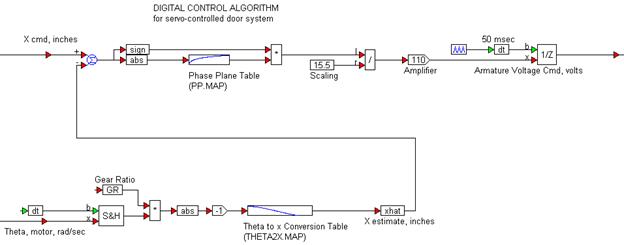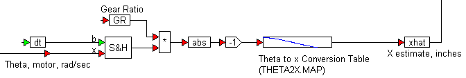
The controller takes two inputs: the open/close command and the actual position of the gear-shaft as estimated by the encoder. The encoder feedback is converted into inches, the same units as the command input using simple arithmetic, and the look-up table THETA2X.MAP gives the relationship between angular gear-shaft position and equivalent door-assembly linear displacement as previously seen. The conversion logic is as shown below.
The error is calculated by subtracting the estimated actual door displacement from the commanded displacement. While the absolute value of the error determines the amplitude of the control voltage to be applied, the output of the sign block is used to determine the polarity of the voltage to be applied (that is, whether the door is to be opened or closed).
Another look-up table (PP.MAP) determines the recommended control voltage ratio. The recommended control voltage is converted into a ratio by scaling it with the maximum value from the table (15.5) and fed to a simple proportional control stage represented by a gain of 110. The output of the proportional stage is sampled at 50ms to represent the physical realities of implementing the control logic on a digital target such as a DSP or a microcontroller.
The complete controller structure is as shown below.