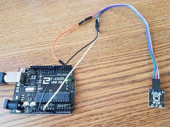
5. Set up the hardware by attaching the pushbutton sensor to the GRND, 3.3V and digital input 2 pins on the Arduino Uno R3.

6. Attach the Uno to your computer using a USB cable.
7. Start Embed and click File > New.
8. Save the diagram as BlinkLEDwithPushButton.vsm.
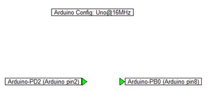
9. Add an Arduino Config block, Digital Input for Arduino block, and Digital Output for Arduino block to your diagram.

10. Wire the Digital Input for Arduino block into the Digital Output for Arduino block and make sure:
•The Arduino Config is set to the proper COMM port.
•The Digital Input for Arduino is set to channel 2 and port PD.
•The Digital Output for Arduino is set to channel 2 and port PB.
11. Generate code to run on the Arduino.
12. After the code has been downloaded to the Arduino Uno R3, click the pushbutton on the sensor. The built-in LED fails to respond when pushing the sensor button.
The next several sections step you through how to debug the code using the Arduino serial monitor.