Site Settings
View the different settings for sites.
Working with Sites and Transmitters
An overview of all sites and transmitters of the current project can be found at and click the Sites tab or the corresponding
toolbar icon ![]() .
.
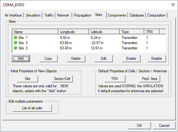
Figure 1. The Project Parameter dialog.
- Add
- Use this button to add a new site to the project. After pressing the button, a dialog opens, where the transmitter type has to be chosen. Besides this, the number of sectors for this site as well as azimuth and tilt values for the specified sectors can be defined here.
Figure 2. The Transmitter Type dialog.
After pressing OK, the parameters of the generated site can be further adjusted with the site definition dialog. In the upper part, the user can modify the parameters corresponding to the site, for example, the location coordinates. In the lower part of the dialog, the transmitters belonging to the sectors of the site can be edited. It is also possible to add or delete transmitters / sectors.
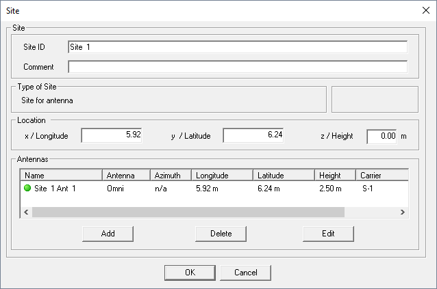
Figure 3. The Site dialog.
- Site
- An arbitrary site ID (name), as well as a comment, can be specified for each site to identify it in the simulation project.
- Type of Site
- Description of the type of current site.
- Location
- Location coordinates (x / Longitude, y /
Latitude, and z / Height) of the site.
Note: The height value is only used for the display of the site on the screen. There is no impact on the prediction. The height defined for transmitters/antennas is used for the prediction.
- Antennas
- List with transmitters/antennas assigned to the site and their most important parameters.
- Copy
- This option can be used to copy an already existing site with all parameters. The site to be copied has to be selected before copying.
- Delete
- Delete a site from the project. The site to be deleted has to be marked in the site list.
- Edit
- After selecting a site from the site list and pressing the Edit button, the user can edit the site with the Site dialog.
- Enable
- By pressing this button, all transmitters belonging to the selected site will be enabled (all transmitters will be considered during the simulation). Single transmitters of a site can be enabled with the transmitter definition dialog.
- Disable
- By pressing this button, all transmitters belonging to the selected site will be disabled (will not be considered during the simulation). Single transmitters of a site can be disabled with the transmitter definition dialog.
Initial parameters for new sites or sectors/cells respectively can be defined by pressing the corresponding buttons shown below. Each new site/sector which is added to the project will have the initial parameters which are defined here.
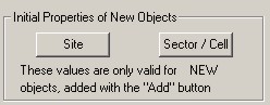
Figure 4. The Initial Properties of New Objects dialog.
Default properties for transmitter antennas and the prediction area can be defined by clicking the TRX or the Pred. Area button, respectively. These values will be used during the simulation if default properties for antennas are selected in the transmitter definition dialog.
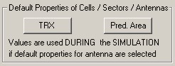
Figure 5. The Default Properties of Cells / Sectors / Antennas dialog.
After clicking the TRX button, you can specify transceiver settings such as cable loss, hardware limitations and receiver noise figure. For the WCDMA air interface, the common powers have to be defined here as well.
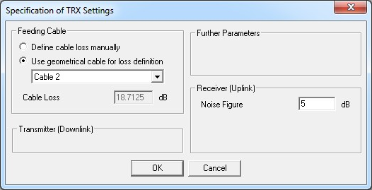
Figure 6. The Specifications of TRX Settings dialog.
- Cable loss
- This parameter represents the loss of the cable between the power amplifier and the antenna of the base station transmitter. The specified cable loss impacts the propagation results only if power mode “Output Power Amplifier” is selected for the transmitter. In case power mode is chosen to be “EIRP” or “ERP” the cable loss does not influence on propagation simulations.
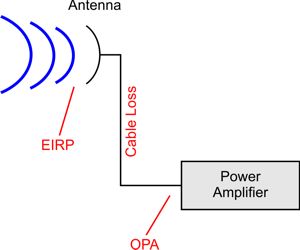
Figure 7. Antenna, power amplifier and cable losses scenario.
In former versions, cable loss was not considered during wave propagation predictions but only in the network planning module. Now and in future releases, cable loss is also considered during wave propagation predictions. This means that the received signal level in each wave propagation result is lower by the cable loss if cable loss is larger than 0.0 dB and “output power amplifier (OPA)” mode is selected. You will be informed about this modification by a message box each time you start a prediction (RUN PRO / RUN NET) within a project based on the old definition of cable losses. You can convert the project to the new cable loss handling by using the menu item Project > Convert Project > Cable Loss Definition.
The prediction area can be defined either by a radius around the transmitters, by corner coordinates or by using the total prediction area as defined at and click the Simulation tab.
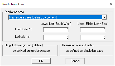
Figure 8. The Prediction Area dialog.