Directional Transmitters
Directional transmitters are used for cellular networks and point-to-point wireless links.
If a directional transmitter/sector antenna is selected (instead of isotropic/omnidirectional), a 3D antenna pattern file must be selected.
These transmitters have the following settings:

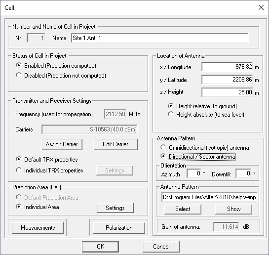
Figure 1. The Cell dialog to adjust directional transmitter settings.
- Number (Nr)
- The number of transmitters is the internal ID and used by ProMan to separate the transmitters of one project. This is not relevant for the project settings.
- Name
- The name of the antenna/transmitter is important because it is added to the basic
output file name. If the basic output file name is xy and the
antenna name is TRX 1 the results will be saved in files
xy_TRX 1.*. Concerning the name of the antenna the following
rules must be considered:
- Only characters can be used which are allowed in file names.
- The name must be unique within the project to avoid collisions with other transmitters.
- Status of Cell / Transmitter in Project
- The transmitter can be enabled or disabled. Only enabled transmitters will be
computed. If no modifications were made, the transmitter can be disabled to save
computation time and so only the modified (and enabled) transmitters are computed
when starting the computation. The transmitter status can also be changed via the
project toolbar using the
 icon and by clicking with the mouse on
the transmitter. The individual cells within the project can be included or excluded
from the network optimization process.
 - Transmitter Settings
- The frequency is defined in this section as well as the output power (which is
required for the determination of the received power or field strength). The output
power can either be defined in Watt or dBm. And the output power can be defined as
one of the following:
- the output power of the PA (power amplifier)
- as effective radiated power (ERP) - for example, relative to dipole antenna
- equivalent isotropic radiated power (EIRP) - for example, relative to an isotropic antenna
- Prediction Area (Cell)
-
- default prediction area
- individual prediction area
- Measurements
- This option can be switched on if measurement data is available for the transmitters included in the project for calibration. This feature allows to automatically calibrate the wave propagation model based on imported measurement data. Supported measurement files are power results (.fpp), field strength results (.fpf) and path loss results (.fpl). The files are generated during the propagation prediction and not during the network computation. These files can then be processed with a separate stand-alone tool to derive the calibrated settings for the propagation exponents (before/after the breakpoint for LOS/NLOS conditions).
- Polarization
- When using GTD/UTD and Fresnel coefficients for the calculation of diffractions or reflections and transmissions, respectively, arbitrary linear polarizations (between +90° and –90°) can be considered for the ray-tracing models (SRT & IRT), the Dominant Path model and the empirical Multi-Wall model. The corresponding polarization can be defined for each Tx antenna individually.
Rural and urban wave propagation simulations do not consider individual polarizations, except if the IRT model is used. If the urban IRT model is not used, vertical polarization is assumed for all transmitters. For rural and urban network planning projects, polarization is only taken into account for the computation of co-channel interference and is not considered during wave propagation prediction.
- Location of antenna
- Location coordinates of the antenna. The same coordinate system as used for the
database must be used. The coordinates can be entered in the dialog or the
transmitter can also be moved/placed with the mouse via the menu : Move or via the toolbar using the
 icon.
icon. - Type of antenna
- A selection between isotropic antenna and directional /sector antenna. An antenna pattern must only be defined if the sector antenna is enabled. If omnidirectional antennas should be considered, an isotropic antenna can be selected, and the gain of the omnidirectional antenna can be added to the EIRP value of the output power.
- Antenna Pattern
- If a sector antenna is selected (instead of isotropic/omnidirectional), a 3D antenna pattern file must be selected. A relative or absolute path can be added. The antenna pattern file can either be in a binary format (.apb) or ASCII format (.apa, .msi, .pln or .ffe)1.
- Vertical Orientation
- You can specify a mechanical down-tilt (positive values) or a mechanical up tilt (negative values). An electrical down tilt must be considered in the selected antenna pattern (the pattern is different depending on the electrical down tilt).
- Horizontal Orientation
- It can be specified more easily with the option Change horizontal
orientation in the Edit -> Transmitter menu. The direction of the
y-axis is 0 degree, the orientation is clockwise (North over East).Switch between omnidirectional and directional antennas and changing the horizontal orientation is done with the function : Azimuth or with the
 icon in the project toolbar.
- Click on a transmitter and then draw a line in the desired direction while holding the mouse button. Then release the mouse button.
- To switch back to an omnidirectional antenna, click on the transmitter and
immediately release the mouse button.Tip: If you have defined a directional antenna you must specify an antenna file using the function and switch or with the
 icon in the project toolbar.