Geostationary Satellite
Calculate indoor satellite coverage from a geostationary communications satellite.
Model Type
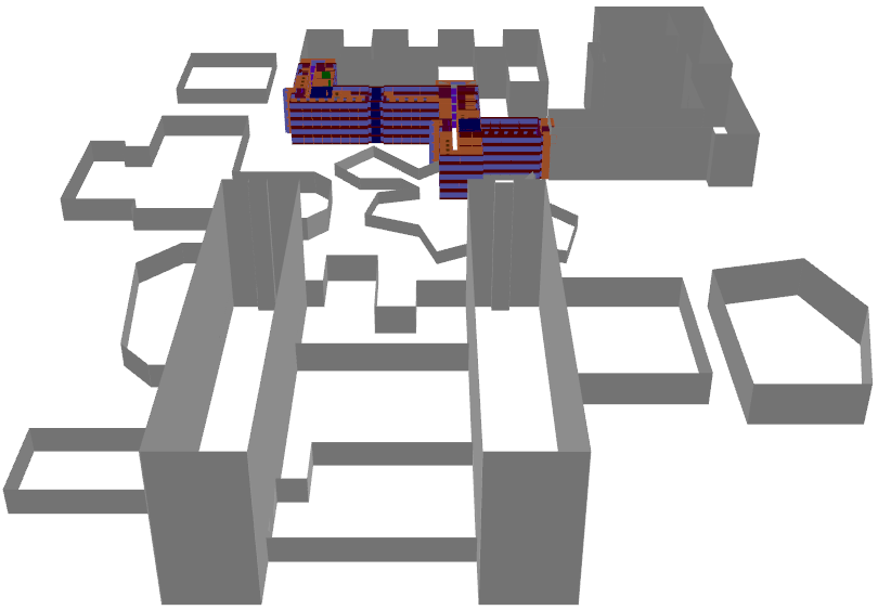
Figure 1. A 3D overview of the indoor database.
Sites and Antennas
A geostationary satellite antenna is positioned at ten degrees longitude and 36,000 km altitude.
In this example, the transmitter power was set to include the high antenna gain.
Computational Method
To see results on the ground floor of the building, the value for the maximum path loss1 was increased to 300 dB.
Results
Propagation results show at every location the power received from the transmitting antenna by a hypothetical isotropic receiver. Figure 2 shows the results inside and outside the building at a height of 1.5 m.
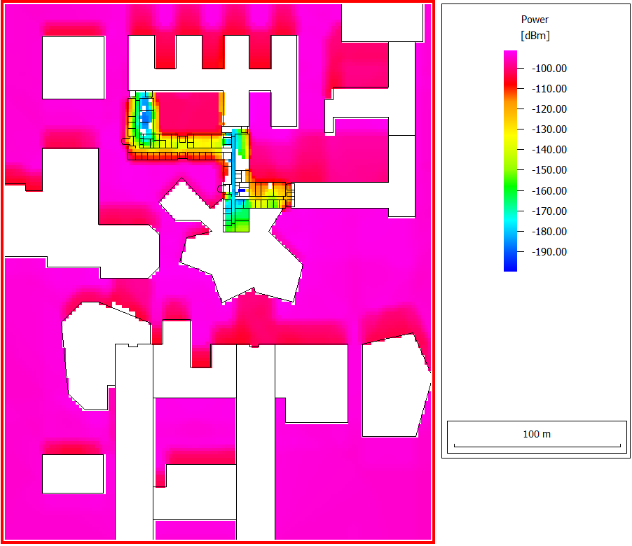
Figure 2. Indoor and outdoor power coverage of the satellite.
The power level outside the building, without any obstructions, is around -94 dBm. In the shadow of a building, this drops to slightly below -100 dBm. Diffraction at the roof edges enables reception when the line of sight is obstructed. An actual receiver would need an antenna with high gain. Inside the building, on the ground floor, power levels are even lower. There is quite a large variation in the received power, depending on how many walls and floors are penetrated.