Create Mesh
In the Periodical Structures module, the mesh generation is a required step that must be performed immediately before simulating. In the Meshing Parameters window, represented in the next figure, the following options are available:
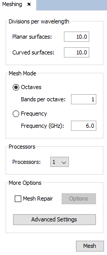
Figure 1. Meshing Parameters panel
Divisions per wavelength The user may specify different mesh density in planar and curved surfaces. Planar surfaces are contained in a single plane, otherwise surfaces are curved. Let c be the speed of light in the vacuum (meters per second), given a number of divisions D and a frequency f, the size of the generated elements L is given by:
L = lambda / D ; lambda = c / f
This parameters are critical for the resolution of the analysis. By default, 10 divisions means that a flat side of 1 meter generate a mesh of 100 elements (10x10 divisions) if the mesh is 0.3 GHz. This module sizes frequently unit cell geometries are in relation to centimeters or millimeters so these values for meshing may not be sufficient to obtain sufficiently accurate results but meshing frequencies rise to the order of GHz or tens of them. In these cases it is recommended to increase this number of divisions for more accurate results, for example to 20 divisions per wavelength.
- Number of bands per octave:
- When a frequency swept is enabled, the meshing frequencies are different to the simulation ones. An automatic frequency ranges per octaves is performed, that depends on the initial frequency, the final frequency, and the number of bands per octave specified. The higher is this parameter, the more frequencies are considered for the meshing process.
- Frequency:Select this option to use the same frequency for meshing all the frequencies of the swept. The frequency must be specified in GHz.
- Processors
- Use this to set the number of processors used for the meshing process.
- Mesh Repair Select this option to evaluate and repair the generated mesh. It is recommended for analyzing complex geometries, specially whenever a good convergence is not achieved. Several problems will be studied and solved isolated and spurious elements are removed, and overlapped regions are repaired. The detection of this defects on the mesh depends on two parameters that are explained below, and can be edited by clicking on Options button. Elements wit smaller area than the minimum allowed, isolated elements, or parallel elements closer than a minimum distance are deleted from the output mesh. The minimum area and distance depends on the wavelength, the number of divisions per wavelength selected, and the Area and Border, and they are determined as:
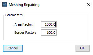
Figure 2. Meshing Repairing options
- The Advanced Settings are explained below.
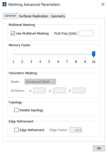
Figure 3. Meshing Advanced Parameters panel (I), General tab
- General there are some options to specify in this tab.
- Multilevel Meshing. Enable this option to generate the mesh automatically in several steps. This option is usually more efficient (in terms of runtime) than common mesh generation, so it is selected by default. However, minor differences may appear between the meshes obtained with and without multilevel mode. The frequency of the first step may be specified by the user in the First freq field, but when this field is empty, the first frequency is automatically computed.
- Memory Factor. This option allows a reduction of the memory resources required in the mesh generation process. The memory allocation is an automatic feature in this process, so the highest one is selected by default to ensure that the mesh will be successfully obtained. If the memory resources exceed the available memory, the message depicted in the next Figure will appear to suggest decreasing this factor.

Figure 4. Warning panel
- Volumetric Mode. This option allows to change the algorithm used in the mesh generation process of dielectric objects (defined as Volumes). Two different modes are available:
-
- Structured Mesh All elements of the volumetric mesh are perfect parallelepipeds. This method is an approximation of the real shape of the dielectric objects by simple cubes. Some parts of the mesh can be out of the volume and other regions can have incomplete regions, but the average volume of the mesh is very similar to the volume of the original dielectric objects. This algorithm is the fastest one.
- Conformed Mesh Most of elements of the volumetric mesh are perfect parallelepipeds, but only in the completely inner regions of them. The inner structured mesh is joined with the boundaries of the volume by using hexahedrons of variable shapes. This method is more accurate than the Structured Mesh, but is also slower and irregular elements may appear in specific cases.
Different divisions per wavelength for the X, Y and Z dimensions may be considered for meshing the volumetric objects.
- Topology. If the electrical continuity between the surfaces have to be broken, the option Disable topology must be selected. Note that the accuracy may be reduced when the electrical continuities are not correctly analyzed because virtual fissures are introduced.
- Edge Refinement. This option allows enabling the modelling of border effect in the mesh generation. The Edge Factor field represents the portion of size of the final elements to model the border effect. It is only enabled when Edge Refinement is selected.
- Surfaces Replication there is only one option called Parameters in this tab that is
composed by some sub-options.
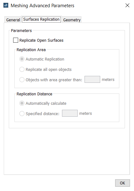
Figure 5. Meshing Advanced Parameters panel (II), Surfaces Replication tab- By marking the Replicate Open Surfaces option, a parallel layer of open objects is generated in the mesh generation process. If replication is marked, the elements of all the open objects are replicated to an automatic frequency-dependent distance from the original ones. By clicking on the advanced button, the window shown in the next Figure will appear where additional features can be configured.
- Replication Area. The criterion to replicate open objects can be edited.
- Replicate all open objects. Any object is replicated, by default.
- Replicate objects with area greater than. To specify manually the threshold of the minimum total area of the objects to be replicated, in square meters.
-
Replication Distance. The distance between the original
objects and their parallel replicas can also be edited.
- Automatically calculate. By default, the distance is given by the following expression:
- Specified distance. To specify manually the desired distance, in meters.
- Geometry the followings parameters can be specified.
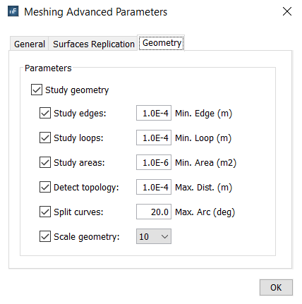
Figure 6. Meshing Advanced Parameters panel (III), Geometry tab- Study Geometry. To pre-process the input geometry, evaluating some features such as its sizes or electrical continuities.
- Study Edges. To delete the edges of the input surfaces that are shorter than the Minimum Edge parameter (in meters), extending its adjacent edges. This option is only enabled when the Study Geometry button is enabled.
- Study Loops. To delete the loops of the input surfaces that are shorter than the Minimum Loop parameter (in meters). This option is only enabled when the Study Geometry button is enabled.
- Study Areas. To delete the input surfaces that are smaller than the Minimum Area parameter (in square meters). This option is only enabled when the Study Geometry button is enabled.
- Detect Topology. To detect automatically electrical continuity between neighboring surfaces that are very close but have not been modeled with precise continuity. The maximum separation allowed to set the electrical continuity is the Maximum Distance parameter (in meters). This option is only enabled when the Study Geometry button is enabled.
- Split Curves. To divide the curved borders of the input surfaces that have a curvature greater than the Maximum Arc parameter (in degrees). This option is only enabled when the Study Geometry button is enabled.
- Scale Geometry. To scale internally the geometry during the meshing process. When the mesh generation finishes, the output mesh has the same sizes as the original geometry. This option is useful for meshing very small structures. This option is only enabled when the Study Geometry button is activated.