General
The General tab has generic advanced parameters that are used by the mesher.
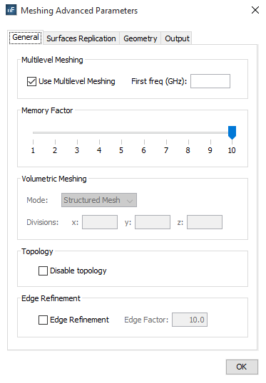
Figure 1. Meshing advanced parameters general tab
- Multilevel Meshing. Enable this option to generate the mesh automatically in several steps. This option is usually more efficient (in terms of runtime) than common mesh generation, so it is selected by default. However, minor differences may appear between the meshes obtained with and without multilevel mode. The frequency of the first step may be specified by the user in the First freq field, but when this field is empty, the first frequency is automatically computed.
- Memory Factor. This option allows a reduction of the memory resources required in the mesh generation process. The memory allocation is an automatic feature in this process, so the highest one is selected by default to ensure that the mesh will be successfully obtained.
-
Volumetric Mode. This option allows to change the algorithm
used in the mesh generation process of dielectric objects (defined as Volumes). Two
different modes are available:
- Structured Mesh All elements of the volumetric mesh are perfect parallelepipeds. This method is an approximation of the real shape of the dielectric objects by simple cubes. Some parts of the mesh can be out of the volume and other regions can have incomplete regions, but the average volume of the mesh is very similar to the volume of the original dielectric objects. This algorithm is the fastest one.
- Conformed Mesh Most of elements of the volumetric mesh are perfect parallelepipeds, but only in the completely inner regions of them. The inner structured mesh is joined with the boundaries of the volume by using hexahedrons of variable shapes. This method is more accurate than the Structured Mesh, but is also slower and irregular elements may appear in specific cases.
- Topology. If the electrical continuity between the surfaces have to be broken, the option Disable topology must be selected. Note that the accuracy may be reduced when the electrical continuities are not correctly analyzed because virtual fissures are introduced.
- Edge Refinement. This option allows enabling the modelling of border effect in the mesh generation. The Edge Factor field represents the portion of size of the final elements to model the border effect. It is only enabled when Edge Refinement is selected.
Note that the memory factor is limited by the available memory in the computer. If the memory resources exceed the available memory, a dialog will appear to suggest decreasing this factor:
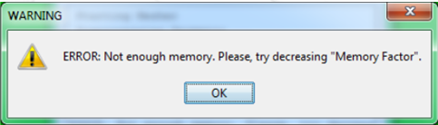
Figure 2. Not enough memory warning dialog.