Editing Project Parameters
As mentioned in previous sections, each module provides each own tree structure to modify the parameters of a project. However, the ways the user can interact with the tree are very similar across all modules.
The nodes below the geometry node are the nodes that are specific to the project and they usually give the user the option to visualize every parameter of the project in a hierarchical and concise way. Additionally, each parameter can be modified in one of the following ways:
-
On/off parameters Some parameters can only be in one of two states enabled or disabled. These parameters are represented in the tree with a checked or unchecked box, respectively, and its state can be toggled between the two states by clicking on them, or by pressing the Enter key while the node is selected.
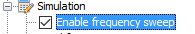
Figure 1. Tree node with a check box -
Numerical parameters Some other parameters have a numerical (integer or real) domain. In these cases, the parameter can be modified by triple-clicking on the node, or by pressing Enter while the node is selected. This will put the node in “edit state”, where the new value for the parameter can be inserted. Once the new value has been written, the user needs to press Enter to confirm this value. If the input value is not valid for the parameter, a error dialog will be shown.

Figure 2. Tree node that represents a numerical value (view state)
Figure 3. Tree node that represents a numerical value (edit state) -
Multiple choice parameters In some cases, the possible values for a parameter belong to a small set of values. To modify these values from the tree, the user can triple-click on a node to display a dropdown menu with every possible value for the parameter, and they can select one of these values to assign it.
Alternatively, the user can press the Enter key while the node is selected to put the node in “editing mode” and press the up and down arrow keys to switch between the possible values. Once the value is selected, the user can press the Enter key to confirm the selection.
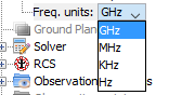
Figure 4. Editing tree node with a predefined set of values -
Drag and drop In some cases, it is possible to drag a node from the tree and dropping it over another node to carry out an action. Examples of this feature include material assignation to surfaces and 3D objects (in which the user has to drag a material node and drop it over a geometry object), material assignation to a ground plane in the Moncros module, or even adding Doppler and Creeping to objects in the PO and GTD modules, respectively. The different uses for this feature will be explained in the following section, “ Drag and drop“.
These types of nodes are usually the leaf nodes of the tree. In addition to this, there can be grayed out nodes in the tree that represent groups of configuration parameters that are not available at the moment due to diverse reasons (for example, because these parameters wouldn’t apply to the currently selected simulation type, or because the functionality is not enabled):

Figure 5. Example of a disabled tree node
Usually, double-clicking these nodes will show a message dialog describing the reasons of why the node is disabled and, if possible, asking the user if they want to enable the functionality associated with the node:
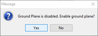
Figure 6. Dialog window asking the user to activate the functionality
If the user answers affirmatively to this question, the functionality will be enabled. In consequence, the tree node will be activated and it will show the corresponding configuration options:
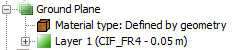
Figure 7. Example of an enabled node