Drag and Drop
Some tasks can be simplified using the “Drag and Drop” feature of the tree. This feature allows the user to perform certain actions by clicking and dragging a node of the tree into another node of the tree.
The uses of this feature are detailed below:
Material assignation to a surface or object
In every module, it is possible to assign a material to a surface or 3D object by just clicking and dragging a material node into a geometry node in the tree.
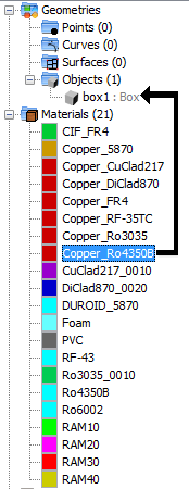
Figure 1. Drag and drop process of assigning a material to an object
Doing this will assign a layer to the object with a default thickness. If the user wants to further configure the layers of an object, they need to use the “Assign” menu option of the “Materials” menu, available in most modules.
Material assignation to a ground plane layer
In the PO and Moncros modules, it is possible to assign a material to a ground plane defined by geometry. To do this, the user needs to drag a material node and drop it into the node that represents the ground plane layer. The user can modify the thickness of each layer from the tree.
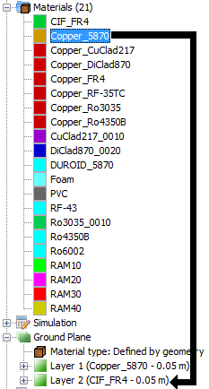
Figure 2. Drag and drop process of assigning a material to a ground plane layer
Creation of observation points from a curve or surface
In the Moncros, GTD and MOM modules, the user is able to extract points from a curve or surface to create a set of observation points used for the analysis of the near field. To do this using the tree, the user needs to drag a curve or surface node into the “Observation points” node. Doing this will show a dialog prompting the user to specify the number of points that will be sampled from the selected curve or surface.
Please, note that:- In order to be able to add a set of observation points in Moncros, bistatic RCS needs to be enabled.
- To add a surface of observation points, it is possible that the user needs to explode the object that represents the surface, so that it appears in the “Surfaces” folder of the tree.
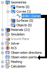
Figure 3. Drag and drop process of adding a set of observation points from a curve
If the user drags a curve node into the “Observation points” node, the following dialog will appear:
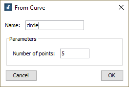
Figure 4. Dialog asking the user how many point samples to extract from the curve
In the other hand, the following dialog will appear if the user does the same with a surface node. In this case, it is necessary to specify the number of points to sample in each direction of the parametric surface.
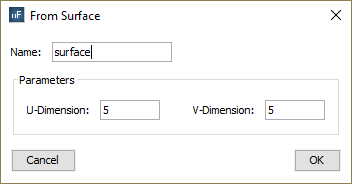
Figure 5. Dialog asking the user how many point samples to extract from the surface, for each parametric direction
When the user presses the “OK” button, the observation points will be added.
Duplicate normals of an object in the PO module
In the PO module, the user can duplicate the normals of an individual surface or all the surfaces of an object by clicking and dragging the object or surface and dropping it in the “Duplicated normals” node.

Figure 6. Drag and drop process of adding a set of observation points from a curve
The list of objects and surfaces with duplicated normals can be found under the “Duplicated normals” node.
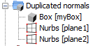
Figure 7. Tree node that shows the list of objects with duplicated normals
In order to cancel the normals duplication of a surface or object, the user needs to right-click the corresponding node and select the “Don’t duplicate normals” option of the popup menu.
Set creeping to an object or surface
In the GTD module, it is possible to add creeping behaviour to an object or surface by just clicking and dragging a object node and dropping it into the “Creeping objects” node. Please nota that the “Creeping” simulation option must be enabled before doing this.
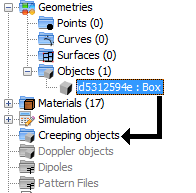
Figure 8. Drag and drop process of adding creeping to an object
The children nodes of the “Creeping objects” node represent the objects that have creeping enabled at the moment. To remove creeping from any of these objects, the user needs to right-click the node and select the “Remove Creeping” option.
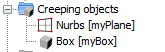
Figure 9. Tree node that shows the list of objects with creeping
Set Doppler parameters to an object
In the PO and GTD modules, the user is able to add doppler parameters to an object. This task can also be done with drag and drop by clicking and dragging the object node and dropping it into the “Doppler” node.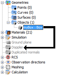
Figure 10. Drag and drop process of adding doppler to an object
The children nodes of the “Doppler” node will represent all the objects with doppler in the current project. This node will also allow the user to modify the doppler parameters for each object (i.e the translation parameters and the rotation parameters, as well as the global parameter “frequency bin”).

Figure 11. Tree node that shows the list of objects with doppler
To delete doppler of an object, the user needs to right-click the corresponding child node of the “Doppler” node and select the “Delete doppler” option from the contextual menu.