Run Analysis and Export FEM File
Define and run a linear static, normal modes, or buckling modes analysis, then export a FEM file.
The analysis includes materials, concentrated masses, and loads and supports, but ignores constraints.
Location: Structure ribbon, Run tools,
Analyze icon.

Run a Structural Analysis
Select a solver, run options, and run settings to run an analysis.
Before running a structural analysis, you must first define one or more load cases containing both loads and supports.
-
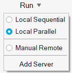
On the Structures ribbon, click the Run group label, then select
whether to run the analysis locally or in the cloud on Altair One. You can also run analysis on
a remote server, either manually or by setting up and using an Altair PBS server. (These
options are only available for OptiStruct analysis.)
-
Select the Run Analysis
 tool on
the Analyze icon to define settings for the analysis.
tool on
the Analyze icon to define settings for the analysis.
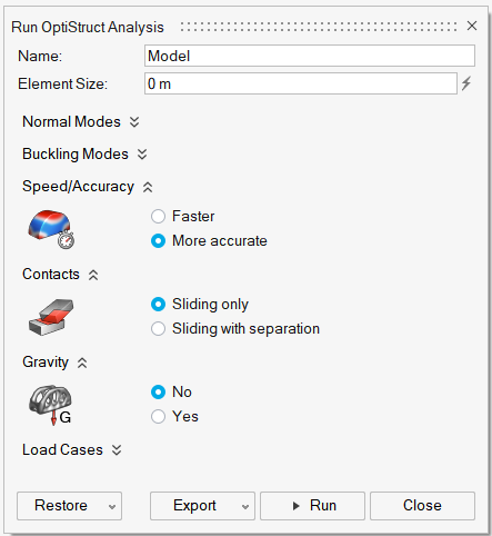
The options will vary based on whether you are running a SimSolid or OptiStruct analysis. Linear static analysis is run automatically, and you can choose whether to run a normal modes analysis. If running an OptiStruct analysis, buckling modes are available as well.Run SimSolid Analysis Run OptiStruct Analysis 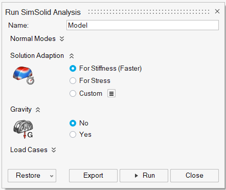
-
If you have created multiple load cases, click the
 button next to Load cases
and then select the checkbox next to each load case you want to analyze. Each load case will
produce a different result.
button next to Load cases
and then select the checkbox next to each load case you want to analyze. Each load case will
produce a different result.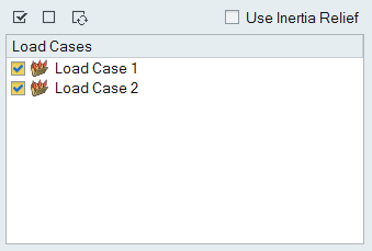
-
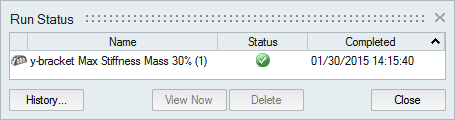
Use the Run Status
 tool to monitor the progress of the run.
-
When the run completes, click the green flag on the Analyze icon or double-click the name
of the run in the Run Status window to view the results.

Tip:
- Once the analysis is complete, you can interactively view the results using the Analysis Explorer.
- You can save or delete runs using the right-click context menu in the Analysis Explorer or Model Browser.
- If you don't want to wait for the run to finish, you can close the Run Status window and continue working in Altair Inspire. You can check on the status of a run at any time by clicking the Run Status tool on the Analyze icon.
- There is no design space for an analysis, so there is no requirement to break up your model into design and non-design spaces and apply loads only to the latter. Any part can be analyzed. However, if you intend to optimize the part later, it is beneficial to split your part into design and non-design spaces and apply appropriate loads and supports prior to running a baseline analysis.
Run Options: SimSolid vs OptiStruct
Use the options on the Run Analysis window to define your analysis. Options vary based on whether the SimSolid or OptiStruct solver has been selected.
| Run SimSolid Analysis | Run OptiStruct Analysis |
|---|---|
|
|
Name
When you run an analysis, the name of the run defaults to the name of the model. However, you can assign your own name to the run in the Run Analysis window.Element Size (OptiStruct)
The element size dictates the quality of your optimization results. In general, the smaller the element size, the more accurate the result, but the slower it will run.Note: To improve overall
performance, when a CAD file is imported the mesh sizes are not calculated and are
shown as Auto. Click the  icon to display the Element Size.
Normal Modes
You can choose whether or not to include normal modes, and how many, in your analysis. The results won't show you the amplitude of each mode, but they will show you around what frequencies they start to vibrate. You may also select whether to include supports from a particular load case in the drop-down menu.Buckling Modes (OptiStruct)
Buckling modes are used to predict when a part will bend or collapse under load. You may select the number of modes and which buckling load cases to include. The resulting buckling load factors help you determine the load required to cause your part to buckle.Solution Adaption (SimSolid)
SimSolid provides three solution adaption objectives to control solution accuracy.
- Select For Stiffness (Faster) for general load path prediction and modes. This uses three adaptive solution passes and is typically the fastest solution method.
- Select For Stress for more detailed stress calculation. This uses four adaptive passes and activates additional logic to more accurately refine the solution in areas of high stress.
- Select Custom to choose your own custom settings in the Preferences.
Speed/Accuracy (OptiStruct)
Select Faster when testing your model to ensure that loads and supports are correct. Once you are comfortable with the results, select More accurate and rerun the analysis to achieve more precise stress and displacement results.Contacts (OptiStruct)
The Contacts option allows you to change the behavior of parts that are contacting. This option is set to Sliding only by default. Changing it to Sliding with separation will produce more accurate results, but will also significantly increase total run time.Gravity
If the weight of a structure is a significant portion of the load it is bearing, then you should include gravity when running an analysis. Gravity pulls toward the negative z direction by default, but you can change the direction using the pull-down menu.Load Cases
A load case is a set of loads and supports that act on a model at one time. You can assign loads and supports to specific load cases using the Model Browser or context menu. Then when you run an analysis, you choose which load cases to include in the Run Analysis window.Inertia Relief
Inertia relief allows the simulation of unsupported structures. Typical applications are an airplane in flight, suspension parts of a car, or a satellite in space. With inertia relief, the applied loads are balanced by a set of translational and rotational accelerations. These accelerations provide body forces, distributed over the structure in such a way that the sum total of the applied forces on the structure is zeroExport a FEM File
Export a .fem or .ssp file using the Export button on the Run Analysis window.
-
On the Structures ribbon, select the Run Analysis
on the Analyze icon.
- Click the Export button on the Run Analysis window. For OptiStruct analysis, you will need to select a unit system for export.
- Choose a directory and a name for your file, then click Save. SimSolid results will be saved .ssp files, and OptiStruct results will be saved as .fem files.
- When the export is complete, double-click the name of the run to open the directory where the results file is located.
Note: Deleting an exported fem will not delete the fem file or
folder. It will just remove the item from the list in the Run Status window.