HM-4900: Create a MADYMO Model
In this tutorial, you will create the MADYMO leg model and define one of the body local coordinate systems.
Load the MADYMO User Profile
In this step, you will load the MADYMO profile in HyperMesh.
-
Click OK.
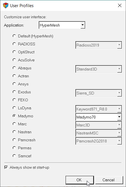
Figure 1. -
Open the Utility menu by clicking from the menu bar.
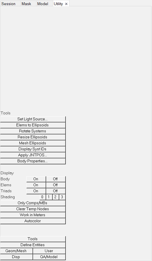
Figure 2.
Retrieve and View the Model File
In this step, you will open the model file and view it in HyperMesh.
-
Open the model file by completing one of the following options:
- Click from the menu bar.
- Click
 on the Standard
toolbar.
on the Standard
toolbar.
- In the Open Model dialog, open the leg_geom.hm file.
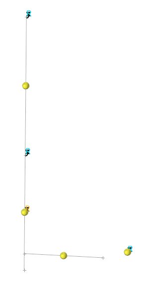
Figure 3.
Create Coordinate Systems
In this step, you will create coordinate systems.
- From the menu bar, click .
- In the panel area, use the origin selector to select the center node of the femur area.
- Using the x-axis selector, select a node along the length of the leg.
- Using the xy-plane selector, select the node along the foot.
- Click create.
- Click return to exit the Systems panel.
Create the Femur Body
In this step, you will create the femur body.
- In the Model Browser, right-click and select from the context menu.
- In the Create multibody dialog, Name field, enter femur.
- Set card image to RIGID.
- Using the Center of gravity: Node selector, select the highest yellow temp node (at the center of the femur).
- Set Creation method to Body system.
- Click Create.
- In the Card Image dialog, enter 6.0 in the MASS field and 0.1 in the moments of inertia field.
- Click return to save changes to the body's card image and close the Card Editor.
- Remain in the Multibody: Create panel.
Create the Tibia Body
In this step, you will create the tibia body.
- Enter tibia in the name= field.
- Click card image = and select RIGID from the pop-up list.
- Double-click N1 to enter the Node Vector Edit sub-panel.
-
Enter the following:
- For x, enter 0.0.
- For y, enter 0.0.
- For z, enter -0.85.
- Click return.
- Click the yellow system selection box under use this system: to make it active.
- Select the orange coordinate system at the center of the tibia.
- Click create/edit to create the body and bring it up in the Card Editor.
- Set MASS to 5.0 and the moments of inertia to 0.1.
- Click return to save the changes to the body's card image and close the Card Editor.
- Remain in the Multibody: Create panel.
Create the Ball Body
In this step, you will create the ball body.
- Enter ball in the multibody name = field.
- Click card image = and select RIGID from the pop-up list.
- Click once on N1 to make it the active selector.
- Select the yellow temp node at the center of the ball.
- Click the yellow system selection box under use this system: to make it active.
-
Click the system box again.
- In the Id= field that pops up, enter 7 to select the orange coordinate system at the ball center.
- Click create/edit to create the body and bring it up in the Card Editor.
- Set MASS to 0.1 and the moments of inertia to 0.01.
- Click return to save changes to the body's card image and close the Card Editor.
- Remain in the Multibody: Create panel.
Create the Ground Body
In this step, you will create the ground body.
- Enter ground in the multibody name= field.
- Click card image = and select RIGID from the pop-up list.
- Double-click N1 to enter the Node Vector Edit subpanel.
-
Enter the following:
- For x, enter 0.0.
- For y, enter 0.0.
- For z, enter -1.1.
- Click return.
- Click the switch to change the value to use body’s local system.
- Click create to create the body.
- Click return to leave the Multibody: Create panel.
Create Geometry
In this step, you will create geometry.
Create Joints
In this step, you will create joints using the create joints panel.
-
Create the Knee Joint.
-
Create the hip joint.
-
Create the Ball Joint
- Enter ball in the name = field.
- Click type = and select FREE from the pop-up list.
- Click the syst entity selection box under parent: and enter 8 in the id= field.
- Click the syst entity selection box under child: and enter 9 in the id= field.
- Keep the parent body set to reference space.
- Click on the ball ellipsoid in the model window to select its body as the child body.
- Click create to create the joint.
- Click return to leave the panel.
Define Systems of Bodies
In this step, you will define systems of bodies.
Define the Initial Conditions and Position the Leg
In this step, you will define the initial conditions and position the leg.
Apply Gravity and Create Vector Data
In this step, you will apply gravity and create vector data in HyperMesh.
-
Click Close to close the Curve Editor.
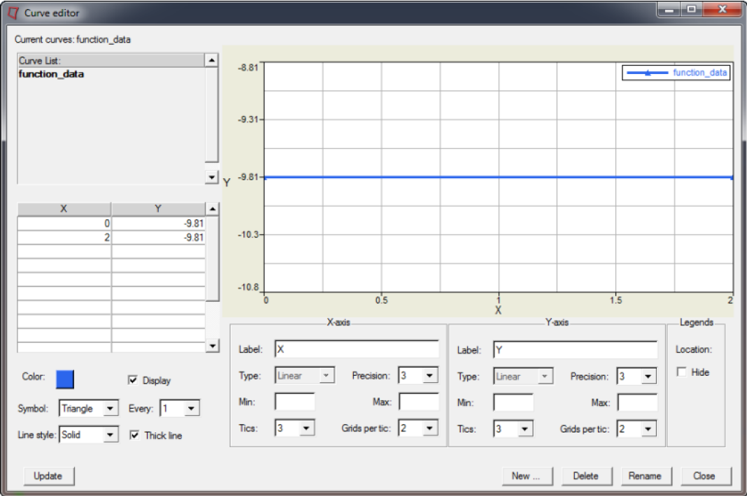
Figure 4.
Apply the Gravity Vector to the Dummy
In this step, you will apply the gravity vectory to the dummy.
- Right-click on the leg_system assembly in the Model Browser and pick Card Edit.
- Activate the LOAD.SYTEM_ACC checkbox.
- Click once on the yellow AZ_FUNC curve selection box to make it active.
- Click on AZ_FUNC and select function_data.
- Click return to save the changes and leave the card image.
- Click return to exit the Card Editor panel.
- Repeat steps 1 through 5 for ball_system.
Create Ball Ellipsoid Characteristics
In this step, you will create ball ellipsoid characteristics.
-
Create the function curve using the Curve Editor.
-
Set the Line style field to Solid.
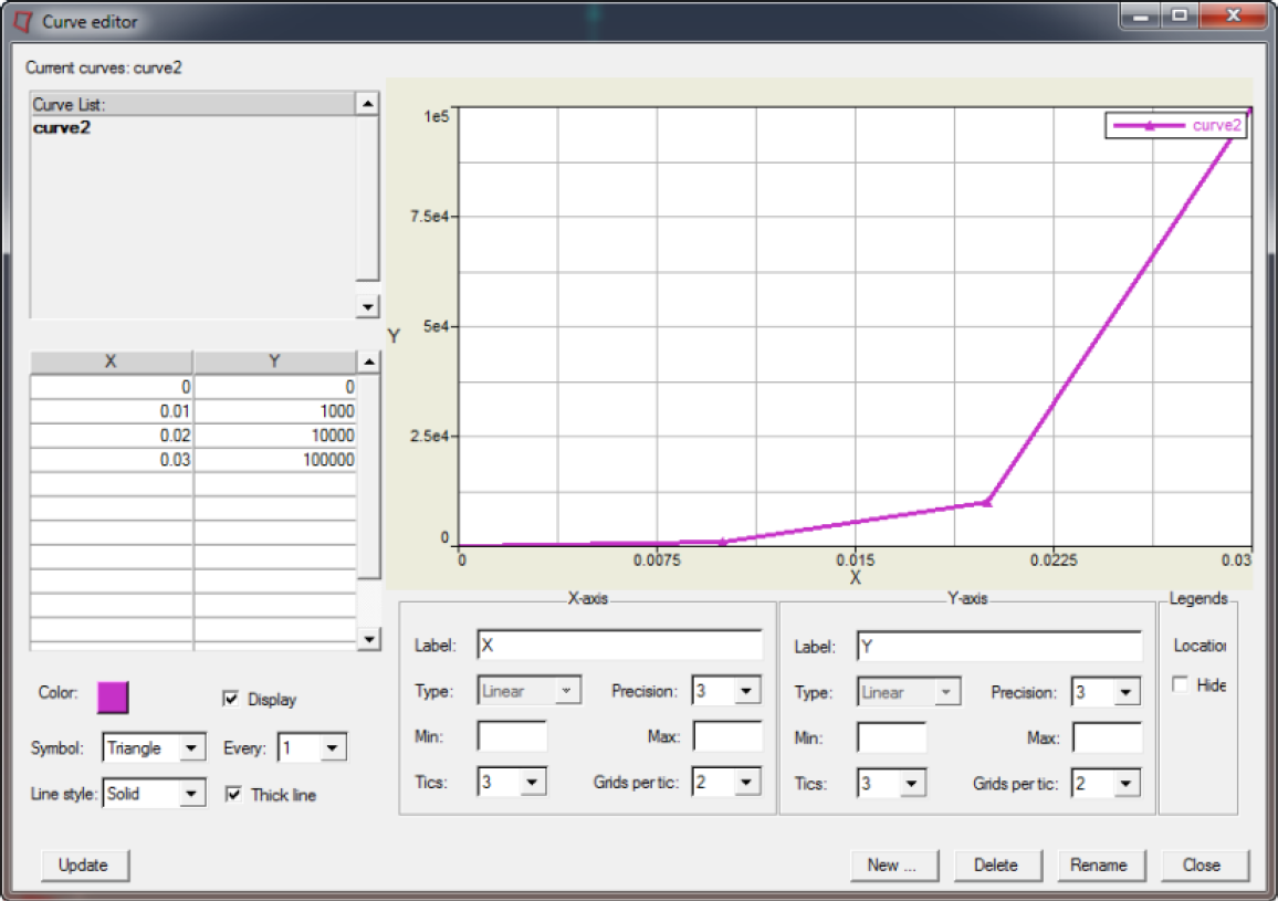
Figure 5.
- Click Update.
- Click Close.
-
Set the Line style field to Solid.
-
Create the property for the ellipsoid.
-
Click LOAD_FUNC and select the created
characteristic curve2.
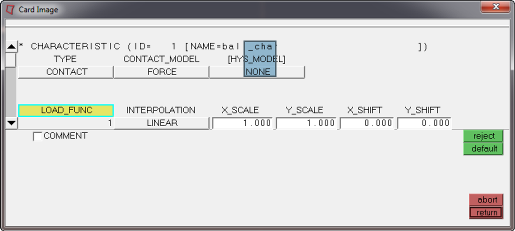
Figure 6.
-
Click LOAD_FUNC and select the created
characteristic curve2.
-
Assign the characteristic.
-
Select ball_char.
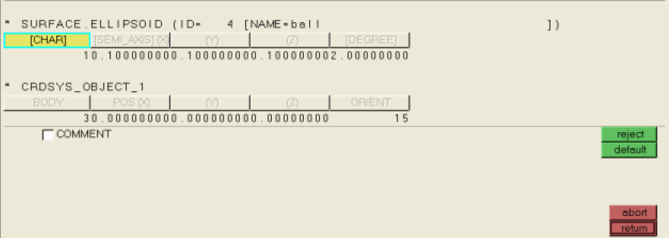
Figure 7.
-
Select ball_char.
Define Contacts
In this step, you will define Contacts in the Contacts panel.
-
Create a GROUP for the foot contact surface.
-
Create a GROUP for the ball contact surface.
- Enter ball_ellipsoid_list in the name= field.
- Click the toggle next to entity to set the selector to ellipsoids.
- Select the ball ellipsoid.
- Click create to create the entity set.
- Click the toggle next to entity to set the selector to sets.
- Enter ball_group in the name= field.
- Click on the sets selection box.
- Activate the ball_ellipsoid_list checkbox and click select.
- Click create to create the entity set.
- Remain in the Entity Sets panel.
-
Create a GROUP for the ground contact surface.
-
Define the Ball to Foot contact.
- Click .
- Activate the create radio button.
- Enter ball_to_foot in the name= field.
- Click type= and select MB_MB from the pop-up list.
- Click create to create the contact definition.
- Activate the add radio button.
- Click twice on the master sets selection box.
- Activate the ball_group checkbox and click select.
- Click the master update button.
- Click twice on the slave sets selection box.
- Activate the lower_leg_group checkbox and click select.
- Click the slave update button.
- Remain in the Contacts panel.
-
Define the Ground to Ball contact.
- Click the create radio button to open the subpanel.
- Enter ground_to_ball in the name= field.
- Click type= and select MB_MB from the pop-up list.
- Click create to create the contact definition.
- Activate the add radio button.
- Click twice on the master sets selection box.
- Activate the ground_group checkbox and click select.
- Click the master update button.
- Click twice on the slave sets selection box.
- Activate the ball_group checkbox and click select.
- Click the slave update button.
- Activate the card image radio button in the Contacts panel.
- Click the green edit button.
- Enter 0.1 for FRIC_COEF.
- Click return to leave the card image panel.
- Click return to exit the panel.
Export and Run the Model
In this step, you will export and run the model.
- Right-click on the MADYMO_Model assembly in the Model Browser and click Card Edit.
- In the card image, enter 0.05 in the TIME_END field.
- Click return to save the changes and exit the card image.
-
Click
 to
export the MADYMO file.
to
export the MADYMO file.
- Use the File Browser to specify an XML filename and click Save.
- Solve the saved file using the MADYMO solver.
- View the results by loading the KIN3 file.