HM-3400: Create Connectors
In this tutorial you will learn how to weld two front trusses by creating connectors between geometry surfaces at pre-defined weld points.
- Weld the two front trusses to each other by creating connectors at pre-defined weld points
- Weld the two front trusses to the reinforcement plate by creating connectors between shell elements
- Weld the right rails to each other and to the front trusses by creating connectors from a master connectors file
- Update weld type of Nastran/OptiStruct ACM (area contact method) welds, which already connect the rear trusses to each other, by first creating connectors from these welds and then realizing the connectors into two-noded weld elements
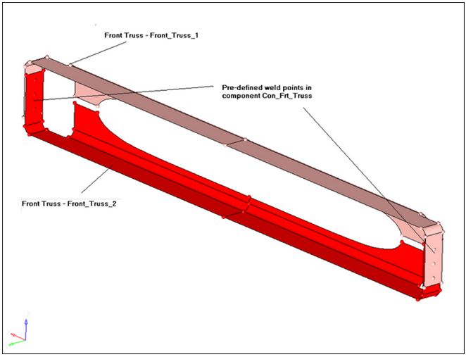
Figure 1.
Open the Model File
In this step you will open and view the model file.
-
Open a model file by clicking from the menu bar, or click
 on the Standard toolbar.
-
On the Visualization toolbar, click
 to
shade your model's geometry and surface edges.
to
shade your model's geometry and surface edges.
Display Only the Assembly
In this step you will display only the assembly assem_1 for elements and geometry.
-
In the Model Browser, click
 (Model View).
-
Set the entity selection to
 (Elements and Geometry).
Note: This options turns on/off both elements and geometry when you perform right-click operations in the Model Browser.
(Elements and Geometry).
Note: This options turns on/off both elements and geometry when you perform right-click operations in the Model Browser.
Load the Connector Browser
In this step you will load the Connector Browser.
-
Review the layout of the Connector Browser. Currently,
there are no components or connectors listed because there are no connectors in
the model.
Note: Use the Connector Browser to view and manage connectors. The top portion of the browser is referred to as the Link Entity Browser, and it displays information about linked entities. The middle portion is referred to as the Connector Entity Browser, and it contains a list of the connectors in your model. The bottom portion of the browser is referred to as the Connector Entity Editor, and it displays attributes assigned to the connector(s) selected in the Connector Entity Browser. The connectors are grouped based on their connection type.
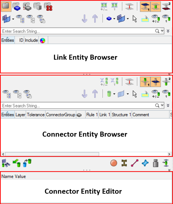
Figure 2.
Create Welds between Geometry
In this step you will create welds between geometry for the two front trusses at the pre-defined weld points.
Connectors can be created automatically or manually. The automatic approach creates and realizes connectors automatically. The manual approach allows you to create and realize connectors manually. Realization is the process in which the connector creates the weld entity.
Use the Spot, Bolt, Seam, and Area panels to create connectors automatically within the Connector Browser, and use the create and realize subpanels to create connectors manually.
-
Verify that the current component is
Con_Frt_Truss.
Note: The current component is always boldfaced in the Model Browser, Component folder.
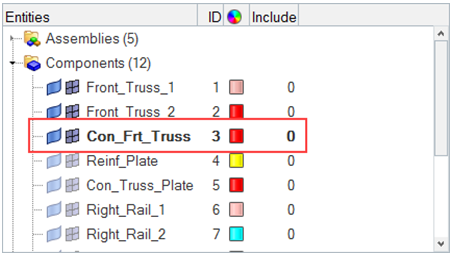
Figure 3. -
Select the component Con_Frt_Truss.
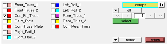
Figure 4. -
Under connect what, switch the toggle from elems to
geom.
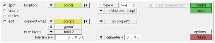
Figure 5. -
Click create.
HyperMesh automatically creates and realizes six connectors (Status bar reads, "6 spot connectors created, 6 realized."), and organizes them as geometry (not elements) in the current component collector, Con_Frt_Truss.Note: Green connectors indicate that the creation of the weld entity was successful.There are four states of connectors: realized (green
 ), unrealized (yellow
  ), failed (red
  ), and modified (blue
  ).
If connectors were created manually, the color of the connectors changes
from yellow to green, which indicates that they are realized into weld
elements. As mentioned above, if you create connectors automatically
they will be green immediately as there is no interim unrealized
(yellow) state.
).
If connectors were created manually, the color of the connectors changes
from yellow to green, which indicates that they are realized into weld
elements. As mentioned above, if you create connectors automatically
they will be green immediately as there is no interim unrealized
(yellow) state.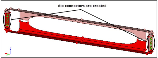
Figure 6.HyperMesh also adds fixed points to the surfaces at the ends of the weld elements to guarantee connectivity between the weld elements and the shell mesh that will be created on the surfaces.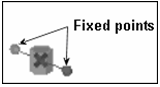
Figure 7.
Review the Connector Browser
In this step you will review the Connector Browser.
-
In the Link Entity Browser, right-click on Front_Truss_1
and select Find from the context menu.
The component is isolated in the graphics area and highlights the six connectors in the Connector Entity Browser to indicate that these connectors have Front_Truss_1 as a link.
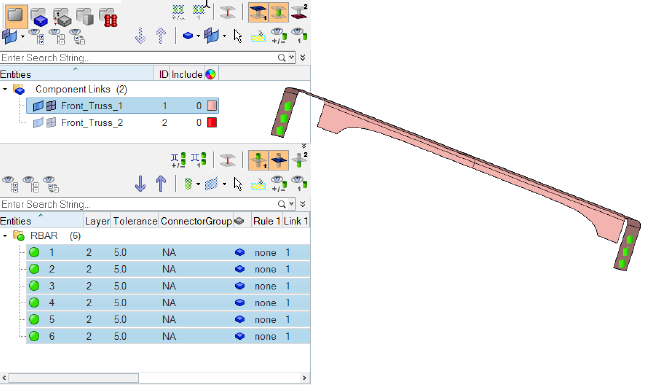 Figure 8.
 -
Right-click on Front_Truss_1 and select Find
Attached from the context menu.
HyperMesh finds the components that are attached to Front_Truss_1 through the connectors.Note: Front_Truss_1 and Front_Truss_2 are now both highlighted in the Link Entity Browser, which indicates that they are displayed in the graphics area.
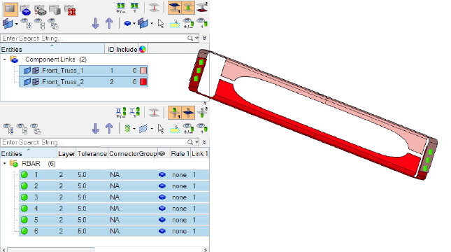 Figure 9.
Create a Shell Mesh
In this step you will create a shell mesh on the two front truss components.
Display Only the Assembly
In this step you will display only the assembly assem_2 for elements and geometry.
-
In the Model Browser, set the entity selection to (Elements and Geometry).
-
Right-click on assem_2 and select
Isolate from the context menu.
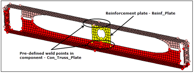
Figure 10.
Create Connectors
In this step you will create connectors between the shell mesh of the front trusses and the reinforcement plate at pre-defined points.
Realize the Connectors
In this step you will realize the undefined, unrealized connectors and assign them a connector type.
-
In the Connector Entity Browser, select the following unrealized connectors: 7,
8, 11 and 12. These connectors are displayed along the top of the Reinf_Plate
component.
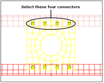
Figure 11. -
In the Connector Entity Browser, select the four remaining unrealized
connectors (9, 10, 13 and 14). These connectors are displayed along the bottom
of the Reinf_Plate component.
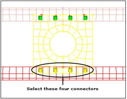
Figure 12. -
In the Connector Entity Browser, right-click on the unrealized connectors and
select Rerealize from the context menu.
HyperMesh realizes the selected connectors and remeshes the mesh to connect the two components.
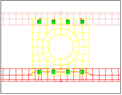
Figure 13.
Display Only the Assembly
In this step you will display only the assembly assem_3 for elements and geometry.
-
In the Model Browser, set the entity selection to (Elements and Geometry).
-
On the Visualization toolbar, click
 to shade your model's elements and mesh
lines.
to shade your model's elements and mesh
lines.
-
Right-click on assem_3 and select
Isolate from the context menu.
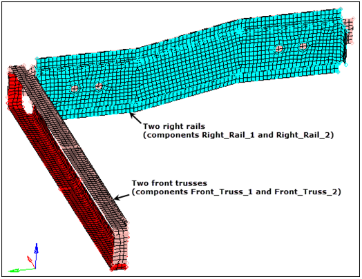
Figure 14.
Create Connectors by Importing Master Connectors File
In this step you will create connectors to connect the right rails to each other and to the front trusses by importing a master connectors file.
-
In the Import tab, click
 in the File field.
-
Click Import.
HyperMesh imports connectors and organizes them into a new component, CE_Locations.Note: It will take a few seconds to import the connectors.
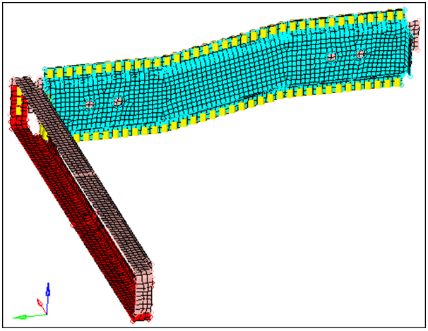
Figure 15.
Realize the Connectors into Weld Elements
In this step you will realize the connectors in the component CE_Locations into weld elements.
-
In the Connector Entity Browser, right-click on the selected connectors and
select Rerealize from the context menu.
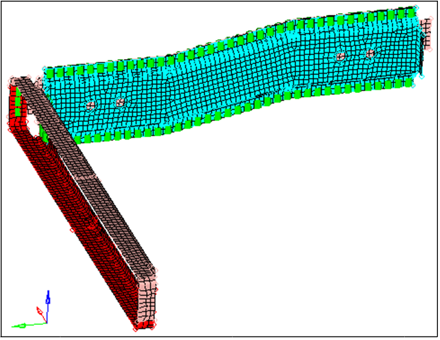
Figure 16.
Display Only the Assembly
In this step you will display only the assembly assem_4 for elements and geometry.
-
In the Model Browser, set the entity selection to (Elements and Geometry).
-
Right-click on assem_4 and select
Isolate from the context menu.
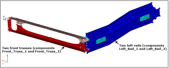
Figure 17.
Create a New Component Collector
In this step you will create a new component collector to hold new connectors.
Duplicate Connectors
In this step you will duplicate the connectors created from the master connectors file and reflect them.
Update the Connectors
In this step you will update the connectors for the left rails and link them to the left rail components.
-
Select the unrealized connectors in the list.
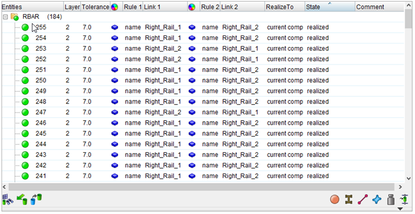
Figure 18. -
Click proceed. Left_Rail_1 is inserted into the Link
Select field.
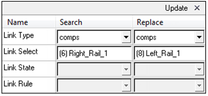
Figure 19.
Realize Connectors into Weld Elements
In this step you will realize the connectors in the component CE_Locations_Dup into weld elements.
Verify Connectors
In this step you will verify that all connectors are realized and identify the pairs of adjacent connectors.
-
On the Visualization toolbar, click
 (Visualization Options).
-
In the Visualization tab, click
 (Connectors).
Isolate Pairs of Connectors
In this step you will isolate the pairs of adjacent 2t connectors identified in the previous step.
-
Right-click and select Find Between from the context menu.
HyperMesh finds and displays 12 connectors between the four components you selected.
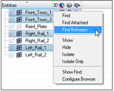
Figure 20.
Unrealize Displayed Connectors
In this step you will unrealize the displayed connectors.
Combine Pairs of Connectors
In this step you will combine pairs of adjacent 2t connectors into 3t connectors.
Realize 3t Connectors into Weld Elements
In this step you will realize the 3gt connectors in the component Con_Frt_Truss into weld elements.
-
On the Visualization toolbar, click
(Visualization Options).
-
In the Visualization tab, click
(Connectors).
Display Assembly Geometry
In this step you will display only the assembly assem_5 for elements and geometry.
-
In the Model Browser, set the entity selection to (Elements and Geometry).
- Right-click on assem_5 and select Isolate from the context menu.
Create Connectors from ACM Welds
In this step you will use the Fe Absorb tool to obtain connectors from the existing ACM welds (elements) in the component, Con_Rear_Truss.
-
Click Absorb.
HyperMesh absorbs the elements into realized, 2t connectors at the locations of the ACM welds, and organizes them into the Con_Rear_Truss component, the same component to which the ACMs belong.
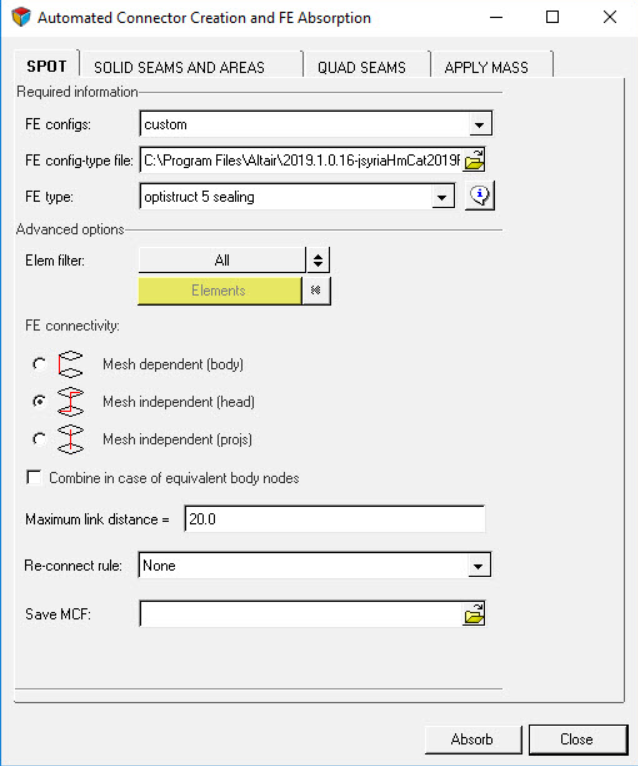
Figure 21.