ACU-T: 5000 Centrifugal Air Blower with Moving Reference Frame (Steady)HyperWorks CFD
Prerequisites
Prior to starting this tutorial, you should have already run through the introductory HyperWorks tutorial, ACU-T: 1000 HyperWorks UI IntroductionPrior to starting this tutorial, you should have already run through the introductory tutorial, ACU-T: 1000 HyperWorks CFD UI IntroductionACU-T: 1000 Basic Flow Set UpHyperWorks CFD, and have a basic understanding of HyperWorks CFD and AcuSolve. To run this simulation, you will need access to a licensed version of HyperWorks CFD and AcuSolve.
Prior to running through this tutorial, copy HyperWorksCFD_tutorial_inputs.zip from <Altair_installation_directory>\hwcfdsolvers\acusolve\win64\model_files\tutorials\AcuSolve to a local directory. Extract from HyperWorksCFD_tutorial_inputs.zip.
Problem Description
The problem to be addressed in this tutorial is shown schematically in Figure 1 and Figure 2. It consists of a centrifugal blower with a wheel of forward curved blades, and a housing with inlet and outlet ducts. The fluid through the inlet plane enters the hub of the blade wheel, radially accelerates due to centrifugal force as it flows over the blades, and then exits the blower housing through the outlet plane. Because they're relatively cheaper and simpler than axial fans, centrifugal blowers have been widely used in HVAC (heating, ventilating, and air conditioning) systems of buildings.

Figure 1. Schematic of Centrifugal Blower
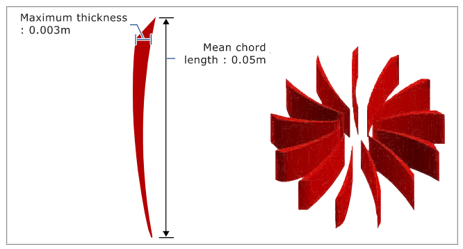
Figure 2. Schematic of Fan Blades