First Ply Failure Method
The Panel_composite config comes with a set of various composite laminates first ply failure criteria. All of these failure criteria are bundled in a single certification method called “First_Ply_Failure”. This method internally invokes former ESACOMP engine.
Despite the method being available under the Panel_composite config, it evaluates failure criteria per element basis. As mentioned before, if the structural property assigned to a given designpoint refers to a user-defined property (PCOMP or PCOMPG), then all attributes required by the method are queried from this property. Otherwise, it will go directly per element’s property (supports PCOMP, PCOMPG, PCOMPP properties and MAT1, MAT8 cards).
All composite stresses are recalculated from shell element forces and moments based on the reference laminate property used. It then requires that result files contain shell element resultant forces and moments.
Math
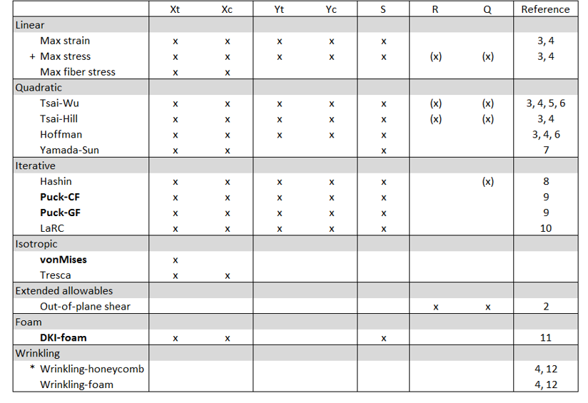
Figure 1. Required allowable per criteria
+ Max stress for isotropic material requires Xt, Xc and S and considers out-of-plane shear.
- R= Transverse_Shear_Allowable_S13
- Q= Transverse_Shear_Allowable_S23
- *E3
The bolded design criteria automatically considers out-of-plane shear stresses.
If R and Q (for MAT8) are defined, traditional in-plane criteria will also consider the out-of-plane shear.
Terminology
Reserve Factor is a measure of margin to the onset of failure. The effective load multiplied with the Reserve Factor gives the design margin. Thus, Reserve Factor values greater than one indicate a positive design margin and values less than one indicate a negative design margin. The values of Reserve Factors are always greater than zero. The term Factor of Safety is used with the Reserve Factor/Inverse Reserve Factor/Failure Index; this is determined as inv(Reserve Factor).
For linear criteria (max strain, max stress and max fiber stress), it is equal to the value of the failure function f.
Margin of Safety = Reserve Factor – 1.
Activate Failure Theories
Once the First_Ply_Failure method is added to a designpointset, you can edit it from the browser. First, you can select the result level (Element | Layer | Recovery plane), then the type of margin to evaluate.
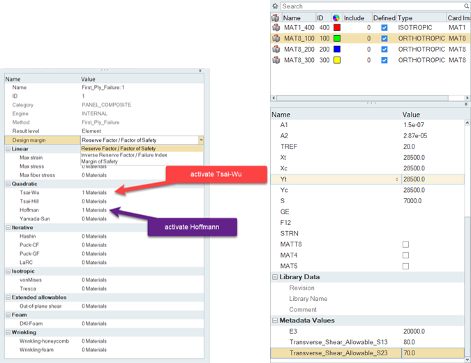
Figure 2. First ply failure selection & allowable as metadata
Example 1: Local Post-Processing
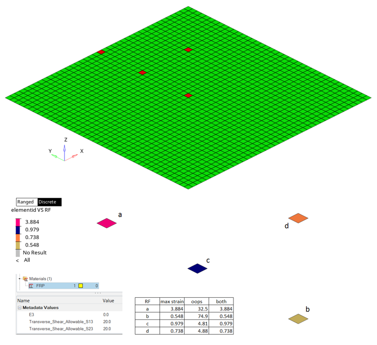
Figure 3.
Example 2: Global Post-Processing
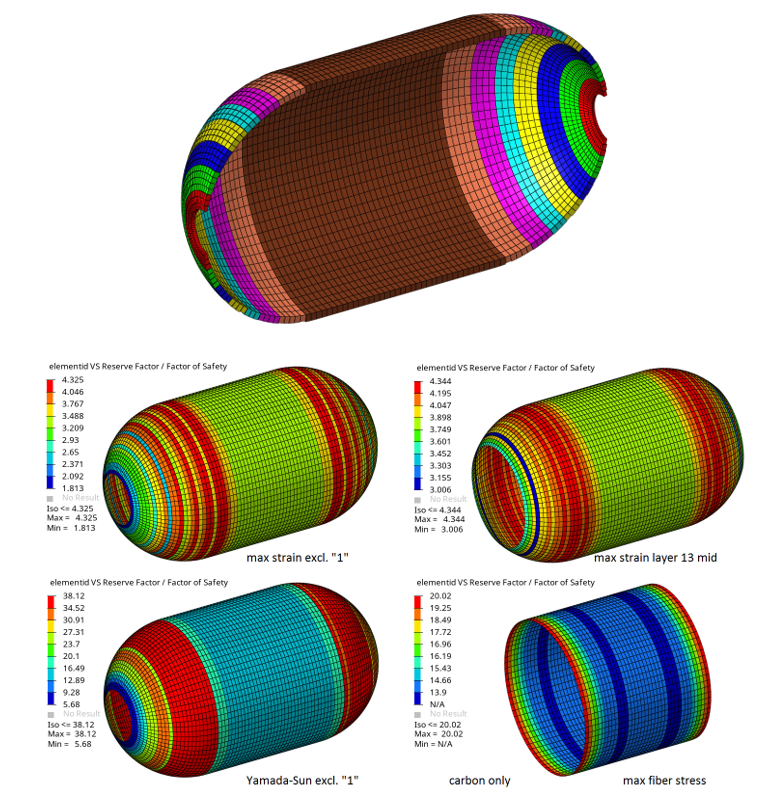
Figure 4.
First Ply Method References
- Mechanics of Composite Materials, Jones, R.M., Hemisphere, New York, 1975.
- Improved transverse shear stresses in composite finite elements based on first order shear deformation theory, R. Rolfes, K. Rohwer, International Journal for Numerical Methods in Engineering, 40:51–60, 1997.
- Failure criteria for an individual layer of a fiber reinforced composite laminate under in-plane loading. ESDU 83014, Amendment A. Engineering Sciences Data Unit, London, 1983/1986.
- Structural Materials Handbook, Volume 1 - Polymer Composites. ESA PSS-03-203, Issue 1. ESA Publications Division, ESTEC, Noordwijk, 1994.
- Introduction to Composite Materials. Technomic, Tsai, S.W. and Hahn, H.T., Westport, CT, 1980.
- Theory of Composite Design, Think Composites, Tsai, S.W., Dayton, OH, 1992.
- A Study of Failure Criteria of Fibrous Composite Materials, Paris F., George Washington University, Langley Research Center, Hampton, Virginia, NASA/CR-2001-210661.
- Failure Criteria for Unidirectional Fiber Composites, Hashin, Z., Journal of Applied Mechanics, 47 (1980), pp. 329-334.
- Failure criteria for non-metallic materials, Implementation of Puck´s failure criterion in ESAComp, FAIL-HPS-TN-003, European Agency Contract Report No. 16162/02/NL/CP, Braunschweig, 2004.
- Progressive failure analysis of advanced composites, Camanho P., NASA FA8655-06-1-3072, June 2009.
- Advanced Material Models for the Creep Behaviour of Polymer Hard Foams; Latest Advancements of Applied Composite Technology, Roth, M. A., Kraatz, A., Moneke, M., Kolupaev, V., Proceedings 2006 of the SAMPE Europe, 27th International Conference, Paris EXPO, Porte de Versailles, Paris, France, 27th - 29th March 2006. ISBN 3-99522677-2-4. pp. 253 - 2258.
- Manual for Structural Stability Analysis of Sandwich Plates and Shells, Sullins, R.T. et al, NASA CR-1457. 1969.
- A higher-order plate element for accurate prediction of interlaminar stresses in laminated composite plates, Ramesh S.S., Wang C.M., Reddy J.N. and Ang K.K., Composite Structures 91 (2009) 337–357.