BasicFEA

Surfaces panel

Surfaces panel

Previous topic Next topic Expand/collapse all hidden text  

Surfaces panel

Previous topic Next topic JavaScript is required for expanding text JavaScript is required for the print function  

Use the Surfaces panel to create surfaces using a wide variety of methods.

The following subpanels create surfaces using specific methods. Each is accessed from a toolbar-like strip of buttons on the Surfaces panel, and some buttons--those with a small arrow in the bottom corner--have multiple values (right-click to change).

surfaceSquare-24 surfaceCylinderFull-24arrowDownMenu-24 surfaceConeFull-24arrowDownMenu-24 surfaceSphereCenterAndRadius-24arrowDownMenu-24 surfaceTorusCenterAndRadius-24arrowDownMenu-24 surfaceSpin-24 surfaceDragAlongVector-24arrowDownMenu-24 surfaceSpline-24 surfaceRuled-24 surfaceSkin-24 surfaceFillet-24 surfaceFromFE-24 surfaceMeshline-24

Note:This toolbar is docked inside the panel and cannot be undocked, moved or hidden.


Subpanels and Inputs


The Surfaces panel contains the following subpanels:

hmtoggle_arrow1Square surfaceSquare-24

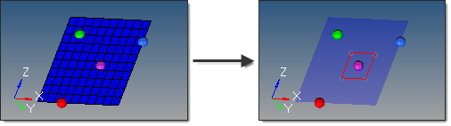
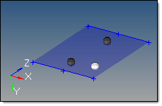
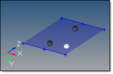
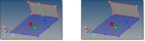
This subpanel creates two-dimensional square surface primitives.

surfaces_square_example

This 10x10 mesh has a new surface created with size 3 centered on the base node; the mesh is set to
transparent in the second image for visibility.

Two values are required to create a square using this method:

The plane in which the square surface lies, including the base node located at the square center.  If a vector is specified, it defines the surface normal.
The size, indicating both the total length and width.  Remember that these dimensions will be centered on the base node, so the resulting square will extend half this value away from it in each direction.


Because you must specify nodes, you must already have suitable nodes in your model or a mesh from which you can pick nodes.  The square subpanel does not contain any tools to create new nodes.


hmtoggle_arrow1Cylinder Full surfaceCylinderFull-24

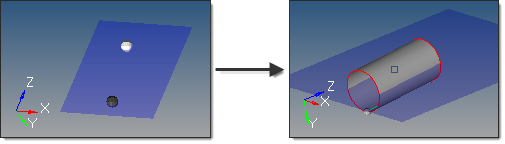
This subpanel creates three-dimensional full cylinder surface primitives.

surfaces_cylinderfull_example

In this example, mesh is set to transparent, and geometry is set to solid with feature lines.  The highlighted
point is the normal vector, and actually extends further from the (gray) bottom center than the height.

Four values are required to create a cylinder using this method:

The bottom center node defines the center of the bottom cylinder face.
The vector between the bottom center node and the normal vector node is the cylinder axis, thereby defining the cylinder orientation.  This does not indicate the actual cylinder height.
The base radius defines the radius of the top and bottom cylinder faces.
The height defines the cylinder height.


hmtoggle_arrow1Cylinder Partial surfaceCylinderPartial-24

This subpanel creates three-dimensional partial cylinder surface primitives.

surfaces_cylinderpartial_example

This example uses Base 1, Height 4, Start Angle 30, End Angle 270, and Axis Ratio 1.

Eight values are required to create a cylinder using this method:

The bottom center node defines the center of the bottom cylinder face.
The vector between the bottom center node and the normal vector node defines the cylinder axis, thereby indicating the cylinder orientation.  This does not indicate the actual cylinder height.
The vector between the bottom center node and the major vector node determines the zero-degree point of an arc defining the curved surface of the partial cylinder.  This arc extends in a direction based on the normal vector using the right-hand rule, with its start angle and end angle specified relative to this vector.
The base radius defines the radius of the top and bottom cylinder faces.
The height defines the cylinder height.
The start angle defines the starting arc angle, measured from the major vector node in a direction based on the normal vector using the right-hand rule.
The end angle defines the ending arc angle, measured from the major vector node in a direction based on the normal vector using the right-hand rule.  The difference between this and the start angle determines the arc of the partial cylinder, and therefore the arc of the cutout in the partial cylinder.  For example, if your start angle is 15 degrees, and your end angle is 285 degrees, the resulting cylinder has a base with a 270 degree arc and a 90 degree cut.
The axis ratio represents a percentage of the major vector.  This value must be greater than zero and less than or equal to 1.  Decimal values create oval-shaped cylinders instead of circular ones.


hmtoggle_arrow1Cone Full surfaceConeFull-24

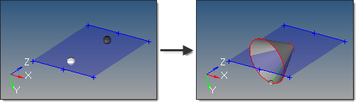
This subpanel creates three-dimensional full cone surface primitives.

surfaces_conefull_example

This example uses a top radius of 0.5, base radius of 3, and height of 4.

Five values are required to create a cone using this method:

The bottom center node defines the center of the bottom cone face.
The vector between the bottom center node and the normal vector node defines the cone axis, thereby indicating the cone orientation.  This does not indicate the actual cone height.
The top radius defines the radius of the top cone face.  If set to 0, a cone tip is created; if greater than zero, the cone has a flat top.
The base radius defines the radius of the bottom cone face.  This value must be greater than 0.
The height defines the cone height.


hmtoggle_arrow1Cone Partial surfaceConePartial-24

This subpanel creates three-dimensional partial cone surface primitives.

surfaces_conepartial_example

This example uses a top radius of 0.5, base radius of 3, height of 4, start angle 45, end angle 320, and
axis ratio 1.0.

Five values are required to create a cone using this method:

The bottom center node defines the center of the bottom cone face.
The vector between the bottom center node and the normal vector node defines the cone axis, thereby indicating the cone orientation.  This does not indicate the actual cone height.
The vector between the bottom center node and the major vector node determines the zero-degree point of an arc defining the curved surface of the partial cone.  This arc extends in a direction based on the normal vector using the right-hand rule, with its start angle and end angle specified relative to this vector.
The top radius defines the radius of the top cone face.  If set to 0, a cone tip is created; if greater than zero, the cone has a flat top.
The base radius defines the radius of the bottom cone face.  Must be greater than 0.
The cone height defines the distance between the cone's base and its top.
The start angle defines the starting arc angle, measured from the major vector node in a direction based on the normal vector using the right-hand rule.
The end angle defines the ending arc angle, measured from the major vector node in a direction based on the normal vector using the right-hand rule.  The difference between this and the start angle determines the arc of the partial cone, and therefore the arc of the cutout in the partial cone.  For example, if your start angle is 15 degrees, and your end angle is 285 degrees, the resulting cone has a base with a 270 degree arc and a 90 degree cut.
The axis ratio represents a percentage of the major vector.  This value must be greater than zero and less than or equal to 1.  Decimal values create oval-shaped cones instead of circular ones.

surfaces_conepartial_example2

This example uses the same settings as the previous one, but with axis ratio 0.5.


hmtoggle_arrow1Sphere Center and Radius surfaceSphereCenterAndRadius-24

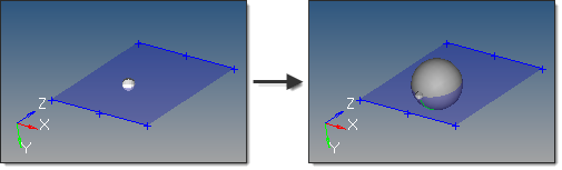
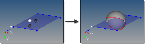
This subpanel creates three-dimensional sphere surface primitives by specifying the center and radius.

Two inputs are required to create a sphere using this method:

The center node defines the center of the sphere.
The radius defines the sphere radius.  A value can be specified, or a node that defines the radius (measured from the center node) can be selected.

surfaces_sphere_centerandradius_example


hmtoggle_arrow1Sphere Four Nodes surfaceSphereFourNodes-24

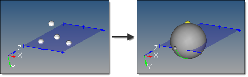
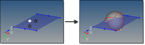
This subpanel creates three-dimensional sphere surface primitives by specifying four nodes.

surfaces_sphere4nodes_example

The selected nodes cannot all be coplanar.  The smallest sphere that passes through all four nodes is created.  If more than four nodes are selected, only the four most recent are used.


hmtoggle_arrow1Sphere Partial surfaceSpherePartial-24

This subpanel creates three-dimensional partial sphere surface primitives.

surfaces_spherepartial_example1

Eight inputs are required to create a sphere using this method:

The center node defines the center of the sphere.
The vector between the center node and R node node defines the first axis of the sphere.
Either a phi node or a theta node to define the second axis and complete the definition of the sphere's orientation.


If the theta node is specified, the theta zero degree angle starts on the vector between the center and R node nodes, and rotates in the plane created by the center, R node, and theta nodes.  This plane also therefore defines the axis for phi, which starts its zero degree angle on the vector extending from the center node normal to the plane defined by the center, R node, and theta nodes.

If the phi node is specified, the phi zero degree angle starts on the vector between the center and R node nodes, and rotates in the plane created by the center, R node, and phi nodes.  This plane also therefore defines the axis for theta, which starts its zero degree angle on the vector extending from the center node normal to the plane defined by the center, R node, and phi nodes.

The radius defines the sphere radius.
The theta begin defines the starting angle for theta.  Valid values for theta are from 0.0 to 360.0.
The theta end defines the ending angle for theta.
The phi begin defines the starting angle for phi.  Valid values for phi are from 0.0 to 90.0.
The phi end defines the ending angle for phi.

surfaces_spherepartial_example2

This example uses theta begin 45, theta end 270, phi begin -30, and phi end 90, while the previous
example uses the same theta values but phi values from -90 to 90.


hmtoggle_arrow1Torus Center and Radius surfaceTorusCenterAndRadius-24

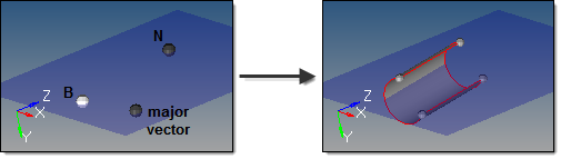
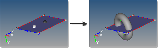
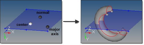
This subpanel creates three-dimensional torus surface primitives by specifying the center, normal direction, minor radius and major radius.

surfaces_torus_centerandradius_example

The highlighted node is the center; the dark one is the normal; this torus has a major radius of 3 and minor
radius of 1.

Four inputs are required to create a torus using this method:

The center node defines the center of the torus.
The vector between the center node and the normal vector node is the torus axis, thereby defining the torus orientation.
The major radius defines the outside radius of the torus, measured from the center node.
The minor radius defines the radius of the circular cross-section of the torus.


hmtoggle_arrow1Torus Three Nodes surfaceTorusThreeNodes-24

This subpanel creates three-dimensional torus surface primitives by specifying three nodes.

surfaces_torus3nodes_example

The nodes define the torus major and minor radii as well as its orientation.

Three inputs are required to create a torus using this method:

The major center node defines the absolute center of the torus.
The minor center node defines the center of the circular cross-section of the torus.
The distance between the minor center node and the minor radius node defines the radius of the circular cross-section of the torus.


The three nodes must define a plane and cannot be collinear. The torus is created perpendicular to the plane, but edge-on relative to the vector between the major center and minor center nodes.


hmtoggle_arrow1Torus Partial surfaceTorusPartial-24

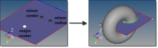
This subpanel creates three-dimensional partial torus surface primitives.

surfaces_toruspartial_example

In this example, the major radius is 3 and major start/end angles are 30 and 270, while the minor
radius is 1 and the minor start/end angles are -120 and 120.

Nine inputs are required to create a torus using this method:

The center node defines the absolute center of the torus.
The vector between the center node and the normal node is the torus axis.
The vector from the center node to the major axis node completes the definition of the torus plane.  Combined with the normal node, this provides the complete torus orientation.
The major radius defines the outside radius of the torus, measured from the center node.
The major start angle defines the starting arc angle for the major circumference (ring), measured from the torus plane in a direction based on the torus axis using the right-hand rule.
The major end angle defines the ending arc angle for the major circumference (ring), measured from the torus plane in a direction based on the torus axis using the right-hand rule.  The difference between this and the major start angle determines the major arc of the torus, and therefore the arc of the major cutout in the partial torus.  For example, if your major start angle is 15 degrees, and your major end angle is 285 degrees, the resulting torus is an open ring with a 270 degree arc and a 90 degree cut.
The minor radius defines the radius of the circular cross-section of the torus.
The minor start angle defines the starting arc angle for the minor circumference (cross-section), measured from the mid-plane of the cross-section in a direction based on the cross-section centerline using the right-hand rule.
The minor end angle defines the ending arc angle for the minor circumference (cross-section), measured from the mid-plane of the cross-section in a direction based on the cross-section centerline using the right-hand rule.  The difference between this and the minor start angle determines the minor arc of the torus, and therefore the arc of the minor cutout in the partial torus.  For example, if your minor start angle is 15 degrees, and your minor end angle is 285 degrees, the resulting torus has a cross-section with a 270 degree arc and a 90 degree cut.


hmtoggle_arrow1Spin surfaceSpin-24

This subpanel creates surfaces by spinning lines or a node list around an axis.

surfaces_spin_example

Seven inputs are required to create a surface using this method:

The lines or node list to spin.

If a node list is specified, a line will first be fit through the specified nodes.

The merge input lines option applies only for lines.

If disabled, a surface is created for each input line, with shared edges connecting surfaces where relevant.

If enabled, the input lines are merged into smooth lines when possible. A surface is created for each group that forms a tangentially continuous line.

surfaces_spin_merged_example
The results on the left preserve the two input lines in the foreground; the image on the right merges them.

The create in method option applies only for lines.  This defines the resulting surface component organization.

Selecting current component organizes the new surfaces to the current component.

Selecting lines component adds the new surfaces to the same component that the selected lines already belong to.  The result is unpredictable if lines from different components become a part of the same surface.

The plane/vector defining the rotation axis.  If a vector is defined or selected, this represents the axis of rotation.  If a plane is defined, the plane normal represents the axis of rotation.

The base node of the plane/vector represents the center of rotation.

The start angle defines the initial angle before the lines/nodes are spun.  The angle is measured about the axis of rotation using the right-hand rule.
The end angle defines the final angle through which the lines/nodes are spun.  The angle is measured about the axis of rotation using the right-hand rule.  The total angle is given by (end angle - start angle).
The direction of the spin.

Spin + is defined using the right-hand rule around the axis of rotation and uses the start angle and end angle values as specified.

Spin - is defined in the opposite direction and uses the negative of the specified start angle and end angle values.


hmtoggle_arrow1Drag Along Vector surfaceDragAlongVector-24

This subpanel creates surfaces by dragging lines or a node list along a vector.

surfaces_dragalongvector_example

The three nodes on the plane define the vector (via the right=hand rule) to drag the selected lines along.

Six inputs are required to create a surface using this method:

The lines or node list to spin.

If a node list is specified, a line will first be fit through the specified nodes.

The plane/vector defining the drag direction.  If a vector is defined or selected, this represents the positive drag direction.  If a plane is defined, the plane normal represents the positive drag direction.
The merge input lines option applies only for lines:

If disabled, a surface is created for each input line, with shared edges connecting surfaces where relevant.

If enabled, the input lines are merged into smooth lines when possible.  A surface is created for each group that forms a tangentially continuous line.

surfaces_dragalongvector_mergeexample
unmerged lines                                        merged lines

The create in method option applies only for lines.  This defines the resulting surface component organization.

Selecting current component organizes the new surfaces to the current component.

Selecting lines component adds the new surfaces to the same component that the selected lines already belong to.  The result is unpredictable if lines from different components become a part of the same surface.

The distance defines the length to drag the lines/nodes along the vector.
The direction of the drag.

Drag + is defined using specified vector direction.

Drag - is defined in the opposite direction.


hmtoggle_arrow1Drag Along line surfaceDragAlongLine-24

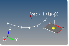
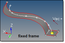
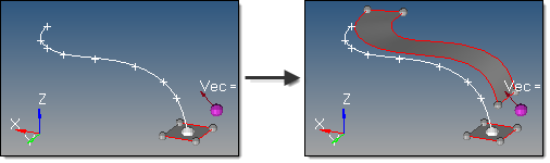
This subpanel creates surfaces by dragging lines or a node list along another line, called the "drag line".

surfaces_dragalongline_example

In this example, the white line is dragged along the dark gray line list one to produce a new surface.

Eight inputs are required to create a surface using this method:

The lines or node list to drag.

If a node list is specified, a line will first be fit through the specified nodes, then dragged:

surfaces_dragalongline_nodesexample

The drag line list that defines the lines that the drag will follow.  This can also be a series of connected lines.
The merge input lines option applies only for lines.
-If disabled, a surface is created for each input line, with shared edges connecting surfaces where relevant.
-If enabled, the input lines are merged into smooth lines when possible.  A surface is created for each group that forms a tangentially continuous line.
The create in method option applies only for lines.  This defines the resulting surface component organization.
-Selecting current component organizes the new surfaces to the current component.
-Selecting lines component adds the new surfaces to the same component that the selected lines already belong to.  The result is unpredictable if lines from different components become a part of the same surface.
The frame mode defines how the lines are translated and rotated during the drag.  In some cases the differences are only apparent when performing relatively complex drags.  The following examples for each frame mode use this starting model:

surfaces_dragalongline_frameexamplestart

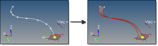
The highlighted line of the rectangular surface is dragged
 along the curved line, which curves in 3 dimensions.

fixed frame: the lines are only translated during the drag, not rotated.

surfaces_dragalongline_fixed

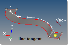
line tangent: in addition to the translation of the fixed frame option, the lines are also rotated in the same way that the tangent of the line list rotates.

surfaces_dragalongline_tangent

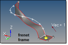
Frenet frame: in addition to the translation and rotation of the line tangent option, the lines also rotate around the line list tangent axis in the same way as the curvature vector rotates.

surfaces_dragalongline_frenet

The Frenet frame option does not work well when the curvature of the line list is not smooth or includes large jumps.

The reference node and transformation plane options require the following definitions:
S: start of drag line (path), which is the closest end of the drag line to the vertices of the line to be dragged. Drag + follows this direction. Drag - follows the opposite direction.

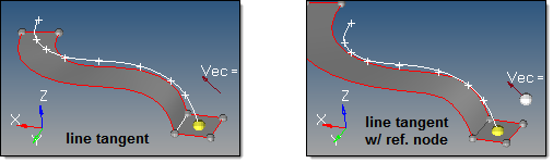
T:  tangent of the drag line at S.

R:  reference node.

B:  base node of the transformation plane.

N:  normal vector of the transformation plane.

The reference node (R) is used to translate the drag (path) line prior to the drag, thus producing results as if the drag line actually began at the selected reference node.  By default, R=S.  If a different S is specified, the line list is translated by the vector defined from S to R.

surfaces_dragalongline_referencenode

The transformation plane is used to translate and rotate the input lines prior to the drag.  By default, no transformation occurs (B=R and N=T).  If specified, the lines are translated by the vector defined from R to B, and are rotated from N to T.

surfaces_dragalongline_transformplaneexample

In this example, R is white and B is purple.

The direction of the drag.

Drag + is defined at the start of drag line, which is the closest end of the line to the line vertices.

Drag - is defined in the opposite direction.


hmtoggle_arrow1Drag Along Normal surfaceDragAlongNormal-24

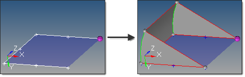
This subpanel creates surfaces by dragging lines along their normal.

Note:Not all lines have a defined normal, but curved lines do.

surfaces_dragalongnormal_example

The yellow arrow indicates the starting normal direction for the selected (white) line.

Six inputs are required to create a surface using this method:

The line list to drag.
The create in method, which defines the resulting surfaces component organization.
-Specifying current component organizes the new surfaces to the current component.
-Specifying lines component adds the new surfaces to the same component that the selected lines already belong to.  The result is unpredictable if lines from different components become a part of the same surface.
The distance defines the length to drag the line along its normal.
-uniform: the line list is dragged a uniform distance.
-variable: the line list is dragged linearly based on a start and end drag value.
The start of the line list is indicated by the end of the chain that has the arrow after selecting the lines, but can be reversed using the switch start point option.
The link type defines how the surface is generated when there is a discontinuity (other than 180 degrees) in the direction of the curvature of the input line list.  There are 2 modes:
-interpolate: the drag direction is interpolated on both sides of the discontinuity to allow a smooth transition.  In this case, along the interpolation region, the drag direction is going to be different than the curvature direction.  Amplified fluctuations, which would occur in the drag because of small ripples in the input curve, are smoothed out with this option.
-no link: no link is inserted if there is a jump in offset direction at points where input lines meet. In this case, the offset lines may become disconnected.

surfaces_dragalongnormal_linktype

The direction of the drag.
-Drag + is based on the curvature of the selected lines and is shown by an arrow at the start of the line list.
-Drag - is defined in the opposite direction.


hmtoggle_arrow1Drag along Normal from Surface icon_drag_along_normal_from_surface

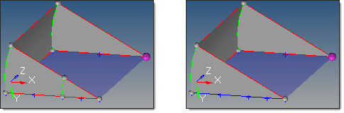
This subpanel creates surfaces by dragging lines along the normal of their adjacent surfaces.

panel_drag_surface_normal_from_surface

Three inputs are required to create a surface using this method:

The lines to drag.  Only surface edges may be selected.
The create in method, which defines the resulting surfaces component organization.
oCurrent component organizes new surfaces into the current component.
oLines component adds the new surfaces to the same component that the selected lines already belongs to. The result is unpredictable if lines are shared by surfaces in different components.
The distance defines the length to drag the line along its adjacent surface normal. Both positive and negative values are accepted. A negative value indicates to use the direction opposite the normal directions.
The direction of the drag. For shared and non-manifold edges, the surface normal is taken from the surface of the main edge. In the event the neighbor surfaces are tangent enough to each other, the average normal is used instead.
oDrag + is defined as the normal directions.  A negative distance value reverses this direction.
oDrag - is defined as the opposite of the normal directions. A negative distance value reverses this direction.


hmtoggle_arrow1Ruled surfaceRuled-24

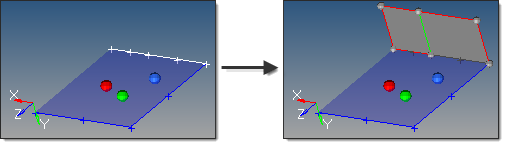
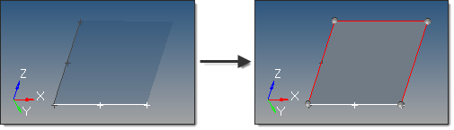
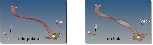
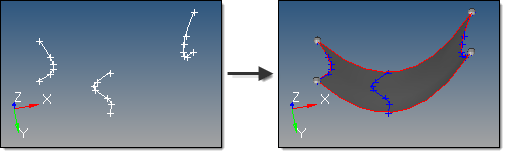
This subpanel creates surfaces by interpolating linearly between lines or nodes.

surfaces_ruled_example

Three inputs are required to create a surface using this method:

The line list or node list that defines the first edge of the surface to create.
-If a node list is specified, a line will first be fit through the specified nodes.
The line list or node list that defines the second edge of the surface to create.
-If a node list is specified, a line will first be fit through the specified nodes.
The auto reverse option prevents "bow tie" surfaces from being generated.  The lines used to create the surface can be ordered in different directions.  This results in a surface that crosses itself resembling a bow tie.  Enabling this option ensures that surfaces are generated with a similar order on each side.


hmtoggle_arrow1 Spline/Filler surfaceSpline-24

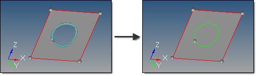
This subpanel creates surfaces by filling in gaps, such as a hole in an existing surface.

surfaces_spline_filler_example

Four inputs are required to create a surface using this method:

lines, node list or points selector defines the spline/filler area.
-If lines are specified, two or more lines must be selected.  The lines do not have to form a closed loop, as disconnected lines are first connected with straight lines.  Both free lines and surface edges can be selected.
-If a node list is specified, a line is created through each node pair and between the first and last nodes in the list. When creating a mesh and surface with nodes, they are automatically stitched to the new surface/mesh by default.
-If points are specified, the order of selection is not important.  A surface is fit through the points using the outermost points as surface vertices.
auto create (free edges only) is valid for free surface edge line selection only.  It creates the surface as soon as a closed-loop free surface edge is selected.  This provides a single-click ability to close holes in an existing surface.  When this option is enabled, surfaces are created in the component of the selected surface edge, and the topology is updated accordingly; when disabled, multiple bounding lines/edges can be selected to create the surface.
keep tangency is valid for surface edge line selection only. This option examines surfaces attached to the selected edges and tries to create a surface tangent to them. This helps to form a smooth transition to the surrounding surfaces.
keep line endpoints for planar splines is valid for surface edge line selection only. This option keeps line endpoints of surfaces created with closed spline/filler lines.
create in defines the resulting surface component organization.
-Selecting current component organizes the new surfaces to the current component.  No topology updates for selected surface edges are made when this option is selected.
-Selecting lines component adds the new surfaces to the same component that the selected lines already belong to. The result is unpredictable if lines from different components are selected. The topology of the new surface is updated accordingly for any selected surface edges that belong to the determined lines component.


hmtoggle_arrow1Skin surfaceSkin-24

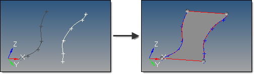
This subpanel creates a surface by skinning across lines.  At least two input lines are required.  Three or more input lines will fit a surface across all of the input lines, with the first and the last input lines defining the surface ends.

surfaces_skin_example

Two inputs are required to create a surface using this method:

The line list defining the lines to use as input.  The lines used to create the skin surface are automatically smoothed before the surface is created.  As a result, the surface is created with a single face.
The auto reverse option prevents "bow tie" surfaces from being generated.  The lines used to create the surface can be ordered in different directions.  This results in a surface that crosses itself, resembling a bow tie.  Enabling this option ensures that surfaces are generated with a similar order on each side.


hmtoggle_arrow1Fillet surfaceFillet-24

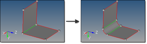
This subpanel creates constant radius fillet surfaces across surface edges.

Note:You cannot create a fillet across free (red) edges between two surfaces; in such a case you must use the edge edit panel to toggle the shared edge (changing it to green).

surfaces_fillet_example

Four inputs are required to create a surface using this method:

The lines defining the surface edges to use as input.
If checked (default), the auto select whole edge option selects additional surface edges connected to the original selection, based on the pick angle and x stop control settings.
-The pick angle applies when the auto select whole edge option is enabled.  The auto selection will select connected edges that have an angle between adjacent surfaces sharper than the specified angle (sharp edges).  Default is 22.5 degrees.
-The x stop control option also applies when the auto select whole edge option is enabled.  If checked, the auto selection will only select edges until it encounters intersections with other sharp edges.
The radius defines the radius of the fillet to create.
The edit fillet options subpanel contains additional, less frequently used options.
-The continuous fillet option creates a single fillet for each continuous edge selection.  If unchecked, the fillet is split based on the surfaces connected to each continuous edge selection.
-The equivalence tol is the tolerance with which the created fillets are stitched to each other and to the original surfaces (after the original surfaces are trimmed by the fillets).  It is also the tolerance with which the trimmed surface chips are stitched to each other if they are not deleted.  This stitching tolerance works just like any other Geometry Tolerance values, but applies only to the fillet stitching operations.
-The trim original surfaces option determines if the original surfaces are trimmed and the new fillet surfaces are stitched accordingly.  If unchecked, the original surfaces are maintained and the generated fillet surfaces are created in a component named "Fillet".
-The delete trimmed surface chips option applies when the trim original surfaces option is enabled.  If checked, the surfaces trimmed from the original model are deleted.  Otherwise, they are kept and organized into a component named "Filleting chips".


Comments

If an edge (or edge chain) is curved, Altair HyperMesh can only fillet with a radius that is smaller than the radius of the edge curve, in order to avoid the fillet intersecting itself.

In addition, care must be taken such that different fillets do not overlap (for example, if two unrelated parallel edges are filleted, the fillet radius must be small enough so that the two fillets do not interfere with each other).

There are known issues in which sometimes fillets are too short, or do not complete the trim of the surfaces being filleted.  Sometimes this leads to a false decision of what should be deleted and what should be kept, and a useful surface is deleted.  Many times, changing the cleanup tol in the Options panel fixes this.  If it cannot be fixed this way, a workaround is to complete the trim manually using other  functions; if needed, uncheck delete trimmed surface chips, create the fillet, complete the trim using manual methods, then delete what is not needed and organize the other surfaces as required.


hmtoggle_arrow1From FE surfaceFromFE-24

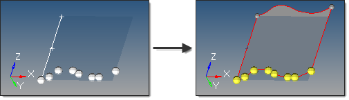
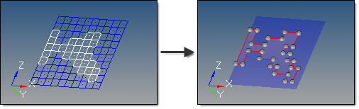
This subpanel creates surfaces that closely fit a selection of shell elements.

surfaces_fromfe_example

In this example the mesh is changed from wireframe to transparent to make the surface more visible.

Six inputs are required to create a surface using this method:

The shell elems that are to be used to generate surfaces.  In order to create surfaces from solid elements, create faces using the Faces panel and select the elements in the ^faces component.
The auto detect features and feature edges options define whether features (surface edges) are automatically determined, or whether they are specified by 1D plot elements (features).
-If set to feature edges, 1D plot elements must be selected to represent the edges of the surfaces to be created.  It is recommended to select a closed loop of plot elements in order to best guide the algorithm.  Features can be created using the Features panel.
-The algorithm used by this function tries to subdivide shell elements into subsets if it does not succeed in creating a single surface through the selected shell elements.
The mesh based auto tol / tolerance options define how closely the new surfaces adhere to the underlying elements.  The tolerance value is the maximum distance by which the surface created differs from the selected elements at any location.  This is particularly important for curved meshes.
-The mesh based auto tol option calculates the tolerance based on the average element size of the selected elements.
-The tolerance option allows a value to be entered manually.  A smaller tolerance usually results in a larger number of surfaces created.
The surface complexity option affects how many surfaces are created.  This option takes into account a number of factors, including the boundary shape of the area to be surfaces as well as its topology.  Higher complexity values create a smaller number of more complex surfaces, but require longer calculation times to create those surfaces.  Smaller values produce a larger number of smaller, simpler surfaces, but do so more rapidly:
-When the complexity is set to 1 (simplest surface), the function attempts to create surfaces with few control points.  If it fails, it tries to subdivide the selected elements until it can fit a lower order surface definition to the elements.
-When the complexity is set to 10 (complex surface), the function first attempts to create surfaces with as few control points as possible.  If it fails, it continues to increase the number of control points and attempts to fit one surface between the selected groups of elements.  It will not try to automatically subdivide the elements.
-The recommended complexity value is 5.
The split by components option maintains boundaries between adjacent components, so that a single mesh plane will still produce separate surfaces based on the components that the elements belong to.
The associate nodes option ensures that the mesh nodes are associated to the new corresponding surfaces.  This allows re-meshing of the surface to replace the original mesh instead of creating a new overlaid mesh.


hmtoggle_arrow1Meshlines surfaceMeshline-24

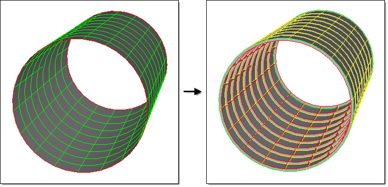
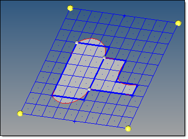
A mesh line is a line on the elements of a 2d (shell) mesh that is associated with the mesh by retaining information about where it enters and exits each shell element.

For a closed chain of mesh lines, you can select the elements or nodes inside the chain and save them as collections for retrieval in other panels.  This can be useful for application of loads, selection of a region to morph, or construction of CAD surfaces close to the mesh using the mesh line chain approximations as the surface borders.

Mesh lines can also be used to generate new surfaces, using a simple spline function to create the surface edges based on the mesh lines.

meshlines_with_surfs

The mesh lines are blue, the surfaces are gray, and the splined surface edges are red.

In addition, meshlines can be generated automatically from plot elements such as feature lines.


Collections

While not related to generating mesh lines, the collections option lets you use existing closed mesh line chains as boundaries to quickly and easily select groups of nodes or elements that may form an irregular shape.  The collections button lets you pick a node or element; if the selection resides inside a closed chain of mesh lines, then all of the nodes/elems within the chain will be selected automatically.  Once this selection is made, you can click the selector and pick save from the extended entity selection menu.  Once saved, this collection of nodes or elements can be retrieved from the extended entity selection menu on other panels, such as load-related panels (forces, pressures, fluxes, and so on. )