|
»Click here to display Table of Contents«
|

Rotate panel |

|

|

|

|
|
Rotate panel |
|
|

|

|
|
»Click here to display Table of Contents«
|
Rotate panel |
|
|
|
|
|
Rotate panel |
|
|
|
|
Use the Rotate panel to rotate entities around an axis in space. The axis of rotation can be selected in several different ways, and the entities rotated can include an entire model or only portions of it.
Notes
|
There are no subpanels on the Rotate panel. All inputs and command buttons are located on the main panel.
Input |
Action |
||||||||
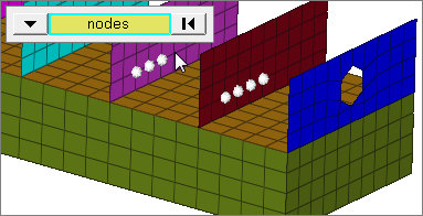
entity selector |
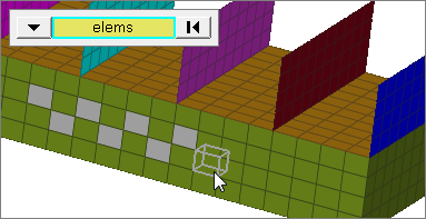
Used to select entities for translation. Valid entity types include nodes, elements, lines, components, surfaces, systems, groups, points, blocks, multibodies, ellipsoids, multibody planes, solids, and connectors. When you select nodes or elems, click the switch to change the selection mode.
|
||||||||
plane selector |
Used to define the axis of rotation.
|
||||||||
angle |
Type the number of degrees (positive or negative) that you want the selected entities to rotate each time you click the rotate + or rotate - button. Click this field twice to access the built-in calculator. |
||||||||
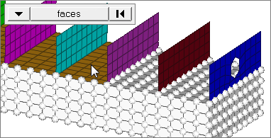
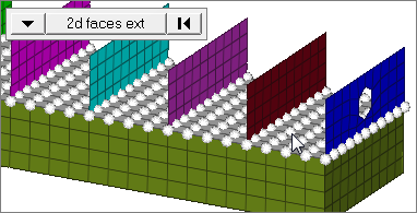
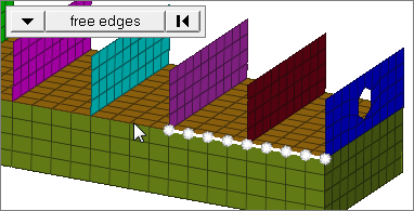
face angle / Individual selection |
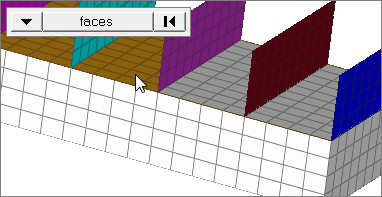
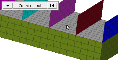
Face angleThe face angle is the angle between the normal of facets that share an element edge. A facet can either be a shell element itself, or one of the faces of a solid element. The normal of triangular facets is that of the plane defined three corner vertices. Whereas, the normal of quadrilateral facets is calculated by taking the cross-product between its two diagonals. This special treatment for quadrilaterals is because a warped shape does not lie completely on a plane. Only available when the entity selector is set to nodes or elems and the selection mode is set to faces, 2d faces ext, free edges, free edges ext, edges, or edges ext.
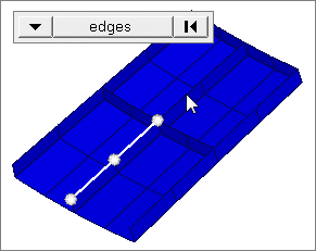
Individual SelectionSelect individual elements on a face or select individual free/shared edges of elements. Only available when the entity selector is set to nodes or elems and the selection mode is set to faces, free edges, or edges. |
||||||||
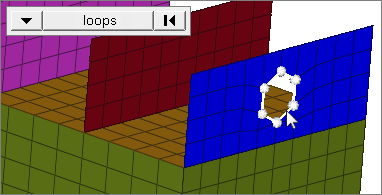
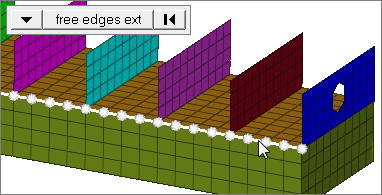
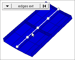
edge angle |
Splits edges that belong to a given face. When the edge angle is 180 degrees, edges are the continuous boundaries of faces. For smaller values, these same boundary edges are split wherever the angle between segments exceeds the specified value. A segment is the edge of a single element. Only available when the entity selector is set to nodes and the selection mode is set to free edges, free edges ext, edges, or edges ext. |
The following action buttons appear:
Button |
Action |
rotate + |
Rotates the selected entities in the positive direction of the rotation axis by the specified angle. Repeated clicks are cumulative. |
rotate - |
Rotates the selected entities in the negative direction of the rotation axis by the specified angle. Repeated clicks are cumulative. |
return |
Exits the panel. |