BasicFEA

BasicFEA Browser

BasicFEA Browser

Previous topic Next topic Expand/collapse all hidden text  

BasicFEA Browser

Previous topic Next topic JavaScript is required for expanding text JavaScript is required for the print function  

Every action performed in BasicFEA is meant to be driven from the BasicFEA browser. First, a geometry file must be imported, which can be any CAD file or HyperMesh database file. Right-click inside the BasicFEA browser and click Open to load the file.          

basicfea_browser

hmtoggle_plus1greyMode

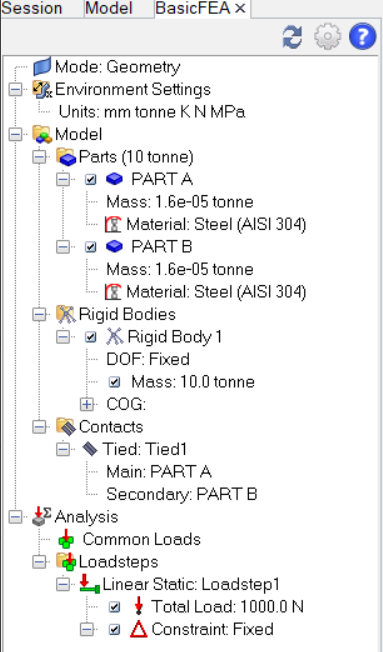
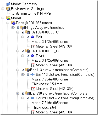
BasicFEA allows you to operate in two different modes: Geometry and Mesh. The Mode listing shows the current state of the model. To change the mode right-click inside the BasicFEA browser and select Mesh mode.    

Mode: Geometry

This is the default setting in BasicFEA. Mesh settings are calculated during import through a volume based algorithm, but no mesh exists while this option is selected.

Mode: Mesh  

Activating Mesh mode applies a mesh on the entire model based on the global mesh settings. These are calculated by default, but can be changed on the global scale or on the individual part level.  

hmtoggle_plus1greyEnvironment Settings

It is important to work in a consistent set of units, and the Environment Settings listing shows the current unit system. The right-click option allows you to change the current working units system. Changing units will convert everything in the model to the new unit system including the model, materials, loads, mesh settings and load size.

The available units can be converted at any time.            

hmtoggle_plus1greyParts

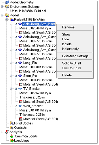
BasicFEA operates under the assumption that every geometric solid is a solid part, and every non-solid continuous surface is a shell part. Therefore the handling of parts remains quite automatic. Parts are not meant to be created, but rather to be a listing of what the model contains. Deleting the part will delete the geometry, the material and load references. Currently if a model has assemblies in it, BasicFEA will show them, but they are not editable.    

browser_parts

Certain visualization tools are also made available on the Parts level: Show, Hide and Reverse.

Analyzing parts made of sheet metal can sometimes be challenging due to the nature of the thin, solid geometry. The solution for these types of parts is to find the “midsurface” of the 3D geometry and operate on that with 2D shell elements that carry the representative thickness. Depending on the type of geometry you are importing, BasicFEA has the following options for Solid to Shell midsurfacing:  

remane_show_hide

3D Solid CAD

If the part is considered a thin solid, you have the option to midsurface the part. This option is called Solid to Shell in BasicFEA. Once midsurfaced, you are left with 2D surface CAD and a thickness representing the midsurfaced dimension. If you run this option within BasicFEA, it saves the solid data, so you can run Shell to Solid and get the solid part back.
If the part is a cast part and is not thin, then it is not a good candidate for Solid to Shell midsurfacing. In this case the option is removed, and BasicFEA operates on the solid part.      

2D Surface CAD

If you have already used some of the advanced midsurfacing tools in HyperMesh, or have 2D surface CAD from another source, you can import it. If it has thickness metadata available, BasicFEA will assign the thickness to the part. If not, it will use the average element size algorithm to give you a starting thickness for each part so that the model can run through.

Solid parts in the BasicFEA browser are represented by theentityComponents-24 icon and have their material displayed as a child. Shell parts are represented by the entitySurfaces-24 icon and have the material child along with a thickness editor that changes the thickness for the entire part.  

hmtoggle_plus1greyMaterial Database

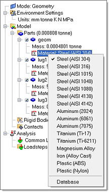
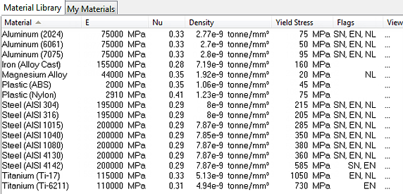
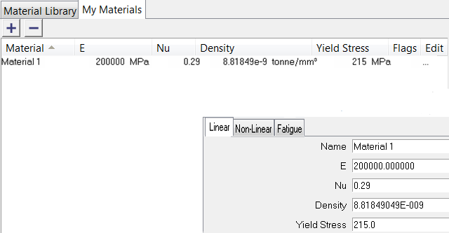
BasicFEA comes ready with linear materials and a limited database of non-linear materials to use. BasicFEA defaults each part to AISI 304 Steel on import, and any of the materials in the library are available to switch between. To change the material of a part, right-click the material underneath the part and a list of available materials will appear.

To open the Material Database dialog either click Database at the bottom of the list or the materialDatabase-24 icon in the BasicFEA toolbar.            

browser_parts_list

mat_db

The option to define a user material is also available through the Material Database. Upon creation of the first user material, BasicFEA creates a file named user_material.xml in the working directory. All user material data is written to this file, which means all user materials are accessible independent of the current BasicFEA or HyperMesh session. Currently linear, non-linear and fatigue isotropic material properties can be created/edited, and all materials are converted between the units within BasicFEA.

edit_mat

hmtoggle_plus1greyRigid Bodies

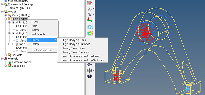
Rigid bodies (rigids, RBE2s, rigid-spiders, RBE3s, and so on) are created, edited and listed one at a time from the BasicFEA browser. Rigid bodies can be a simple way to approximate connections, either as a bolt-style connection within a cylindrical bolt hole or as a connection between parts or surfaces.    

basicfea_rigid_bodies

The following rigid bodies are available:  

Rigid Bodies

Rigid bodies can be thought of as “locking” selected regions together. An independent node is created at the center of the selected regions which is used for loading control. Both forces and constraints are available.  

An option for adding a mass value at the COG that is auto centered upon creation and can have X, Y, Z values edited to represent a part COG is available.  

Sliding Pins

Sliding pins are essentially rigid bodies with nonlinear gaps that act as a pin-style connection. The rigid body itself is created within a tolerance of a selected cylindrical bolt hole and non-linear contact elements are created between the rigid body and the selected structure. The sliding pin connection will only produce non-linear effects with the Non-Linear Quasi-Static loadstep type.

Load Distribution Bodies

Load distribution bodies are used for distributing point loads (forces and moments) to selected regions. Unlike rigid bodies, load distribution bodies add no stiffness to the model. A good way to think about them is in contrast to rigid bodies: If rigid bodies enforce displacement conditions along their selected regions, load distribution bodies enforce consistent loading along their selected regions.  

An option for adding a mass value at the COG that is auto centered upon creation and can have X, Y, Z values edited to represent a part COG is available.  

hmtoggle_plus1greyContacts

Contacts are handled in a simple manner while using BasicFEA. BasicFEA can define tied or sliding type contacts between parts. With this simple part to part contact setup, the solver handles identifying the direct interface or “wetted surface” and applying the appropriate contact forces.            

In addition to manually setting up a part to part contact BasicFEA offers a simple Auto-contact algorithm. The algorithm will search every part in the model and assign a tied contact to parts within the specified tolerance. After creating any contact, manually or automatically, it can be switched between tied or sliding. For sliding contacts a field is available to input friction values.  

hmtoggle_plus1greyAnalysis

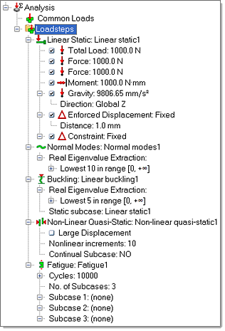
The following loadstep types are available in BasicFEA: Fatigue, Linear Static, Normal Modes, Buckling and Non-Linear Quasi-Static. Constraints, enforced displacements, forces, distributed loads, moments and gravity loads are also available within each loadstep where applicable under the right-click context menu of each loadstep. A Common Loads folder is available by default in the BasicFEA browser. Loads in this folder will be applied to all loadsteps.

basicfea_analysis

hmtoggle_plus1greyLoading Options

Depending on the loadstep type, certain options are available for loading the model:


Constraint

Constraints are available for every loadstep type and are used to constrain the selected portion of the model [point, line, surface or rigid body]. All six degrees of freedom are locked by default, but any DOF combination is available through the right-click context menu.

Enforced Displacement

Enforced displacements can be applied to points, lines, surfaces and rigid bodies. All six degrees of freedom are available to specify the direction, and an input distance is available to specify the displacement value. DOF combinations are available through the right-click context menu.

Distributed Load/Total Load

Distributed loads are essentially pressure loads applied on each element where the total force applied is dependent on the area of the selected surface.

Total Load is acting in a similar way to distributed loads but represents the total load on the surface and calculates the pressure value on each element.

They are applied on surfaces and are available for Linear Static and Non-Linear Quasi-Static loadsteps.

Force

Forces are allowed to be applied to rigid bodies and points.  Applying loads to rigid bodies will reduce singularities, but also allow another method of applying a total load to a surface through rigid bodies. Forces are available for Linear Static and Non-Linear Quasi-Static loadsteps.

Moment

Moments are only allowed to be applied to rigid bodies. This restriction is set to reduce singularities, but also allow for a more realistic application of moments (torque) as a total load to the surface. Moments are available for Linear Static and Non-Linear Quasi-Static loadsteps.        

Gravity

Gravity loads are used to determine gravity loading along a global X, Y or Z vector. BasicFEA sets the scale factor to the acceleration of 1G in whichever unit system you are in. Gravity loads are available for Linear Static and Non-Linear Quasi-Static loadsteps.

hmtoggle_plus1greyMagnitude, Directions and DOFS

Once a load, a constraint and even a rigid body is defined you have options on how to control its magnitude, direction or active degrees of freedom.

Both distributed loads and forces are directional, and BasicFEA offers simple tools to control their magnitude and direction.

[Magnitude]

Once a distributed load or a force is defined a default magnitude and direction is assigned. To change its magnitude left click on the value itself while it is highlighted and the number field will become active; (use the click-pause-click technique). Enter a negative value to reverse the direction.

Global X, Y, Z

To align the load with the global X, Y or Z direction, simply select the option and the load will be updated. These options are available for both distributed loads and forces.

Normal

The normal option is only available for distributed loads and will align the distributed load with the surface normal.

Along Line

The along line direction selector will align a distributed load or force with any selected line in the model. If the selected line is not straight, you will be asked to choose a point (node) along that line. To do this, hold down the left mouse until the line becomes active. Releasing the left mouse will create and select a new node and the position from which the tangent is measured.

Surface Normal

The surface normal selector will align a distributed load or force with any selected surface and point in the model. To do this, BasicFEA will ask for a node. Hold down the left mouse until a surface becomes active. Releasing the left mouse will create and select a new node and the position from which the normal is measured.

Reverse

Reverse will flip the direction of the load by changing the sign of the magnitude.

Choosing the degrees of freedom for a constraint and a rigid body have different meanings, but in BasicFEA the tool used to do so is the same. A constraint will lock whatever is selected in space for whichever degrees of freedom are selected. A rigid body, however, will lock its independent node to the remaining selected dependents. This is what you are actually selecting when creating a rigid body. For most applications, Fixed is appropriate for rigid bodies.


User

The user selection makes it possible to specify the DOF of the entity by entering in the equivalent DOF value 1-6 (Tx, Ty, Tz, Rx, Ry, Rz).

A nice example is the sliding pin. Since a sliding pin by definition only reacts to radial displacements, the axial degrees of translation and rotation must be constrained to stop the pin from “flying out into space.”

Fixed

Fixed signifies locking all the translation and rotational degrees of freedom.  

Translation

Choosing translation for a constraint or rigid body means that the selection is able to rotate freely, but the X, Y and Z translational degrees of freedom are locked. For a constraint this is relative to space, and for a rigid body it is relative to the independent node of the rigid body.

Rotation

Choosing rotation for a constraint or rigid body means that the selection is able to translate freely, but the X, Y and Z rotational degrees of freedom are locked. For a constraint this is relative to space, and for a rigid body it is relative to the independent node of the rigid body.

hmtoggle_plus1greyRight-Click Options

The following right-click context menu options are available:    


New

Clears BasicFEA and deletes the current model from the screen.

Open

Clears BasicFEA, deletes the current model from the screen and allows you to open any geometry file or .hm database file.

Save

Allows you to save the current state of the model to a HyperMesh (.hm) database.      

Save as

Save the file for the first time with a unique file name or allows you to save the current model with a new file name (for example revision number).                      

Dimension mode

Allows you to quickly measure the dimensions of your model.

Scale model only

Scales only the model on the screen without changing the units in BasicFEA. This allows you to match what is on the screen with the unit system after a first import.

Units

Changes the working unit system.

Mesh mode

Geometry mode or Mesh mode. Allows you to switch between the two before an analysis.

Run analysis

If no mesh exists, this will mesh the entire model based on the mesh parameters and launch the solver. While in Mesh mode this will only launch the solver.

Results

Allows you to visualize the results after a solver run. Contour plot, Vector plot and Deformed plot are available. (Select Deformed plot > linear for an animation).

Advanced pre/post

Launches the HyperView client with the results loaded. This option is only available after a solver run.

View report

Opens a simple HTML report generated by the solver after a run in your default web browser.

BasicFEA help

Opens a BasicFEA quick help dialog for an easy walk through.

hmtoggle_plus1greyBrowser Shortcut Icons

For quick reference, the following shortcuts are available at the top right-hand side of the BasicFEA browser.  

shortcut_icons

refresh-24Refresh tree

Refresh is mainly for advanced users, but is a quick way to sync the BasicFEA browser with the HyperMesh database.  

options-24Preferences

Advanced Solver Options, Autocontact Tolerance, Load Display, Language and Global Mesh Settings are all accessed from this shortcut.  

help-24Help

Opens a BasicFEA quick help dialog for an easy walk through.


See Also:

BasicFEA Introduction

Work Flow

Preferences Dialog