Formability Simulation
Learn how to set up a formability simulation.
Open the Model
-
On the Files icon, click the Open Model tool.

Extract the Midsurface
-
On the Extract Face icon, click the Midsurface Thin Solid
Parts tool.

-
On the guide bar, click Midsurface.
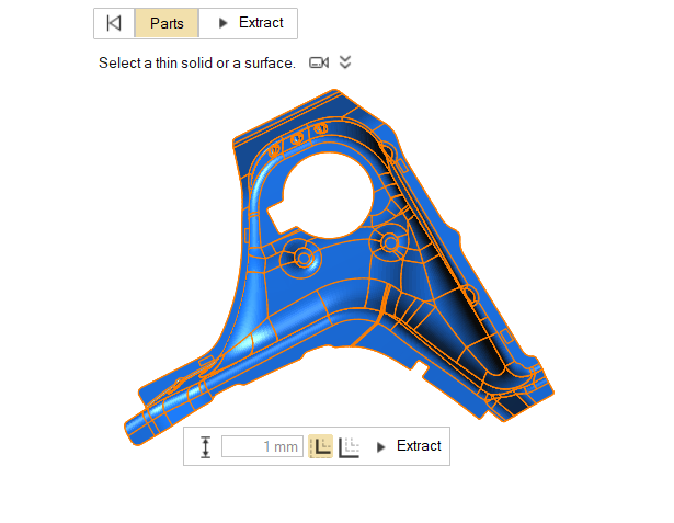
The original thin solid is hidden and deactivated. When the midsurface is created, a thickness is automatically calculated and assigned to the part, and can be viewed in the Property Editor.
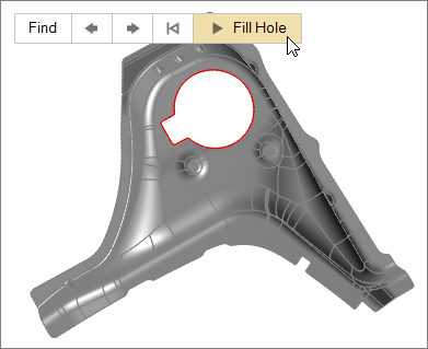
Fill the Hole
-
On the Defeature icon, click the Fill Hole tool.

By default, all of the holes in the model are selected and highlighted red. The total number of holes found is displayed above the Defeature tool group.
-
On the guide bar, click Fill Hole.
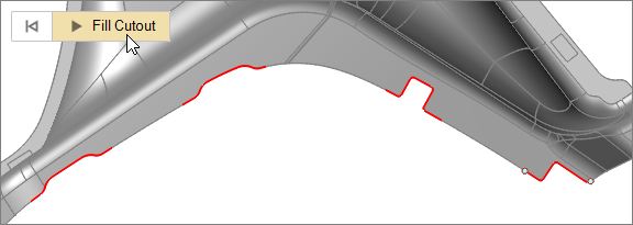
Fill the Cutout
-
On the Defeature icon, click the Fill Cutout tool.
-
On the guide bar, click Fill Cutout.
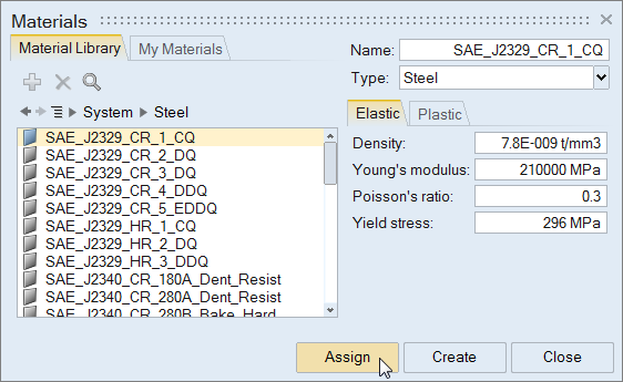
Assign a Material from the System Library
-
Click Close.
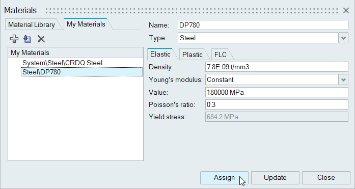
Create and Assign a Material Based on Test Data
Create a new material with test data from a .xlsx file.
-
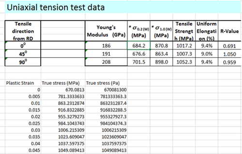
In Microsoft Excel, open and review the file
<installation_directory>\InspireForm2021.2.1\tutorials\Material_Data.xlsx. The data
should look something like this:
Note: You can copy data from an .xls file and paste it directly into the relevant property fields of the Materials dialog in Inspire Form. -
From Inspire Form, on the Tryout tab,
click the Materials icon.

-
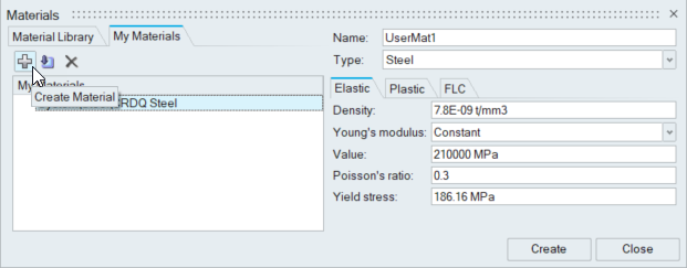
Click the Create Material button:
-
Select the Elastic tab.
-
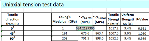
For Yield stress, enter the value from the .xlsx
file: 684.2MPa
-
For Yield stress, enter the value from the .xlsx
file: 684.2MPa
-
In the first cell of the True Strain column, right-click
and select Clear All.
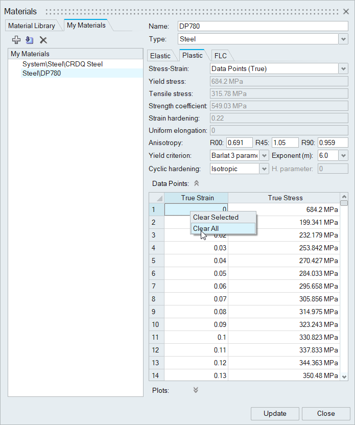
The existing data points are removed. -
Click Assign.
Set the Stamping Direction
-
Click the Orient tool.

-
In the microdialog, click Y.
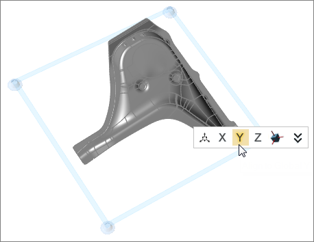 The stamping direction aligns to the global Y axis.
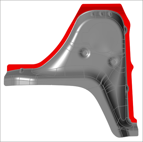
Create a Blankholder
-
Select the blankholder surfaces indicated in the following image.
Blankholder surfaces are pre-grouped and highlighted based on your cursor location. If individually selected surfaces share an edge, they will be grouped together. Surfaces that are selected are highlighted red.
- To select pre-grouped blankholder surfaces, left-click.
- To select individual surfaces, hold the Ctrlkey and left-click.
- To append surfaces to your selection, hold the Ctrl key and left-click.
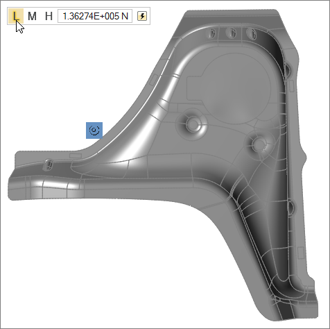
-
To set the force to low, on the microdialog, click
L.
Run the Analysis
-
Run the analysis.
- On the Analyze icon, click the Run Analysis
tool.

- In the Run Analysis window, enter a name for the analysis and click Run.
- On the Analyze icon, click the Run Analysis
tool.
-
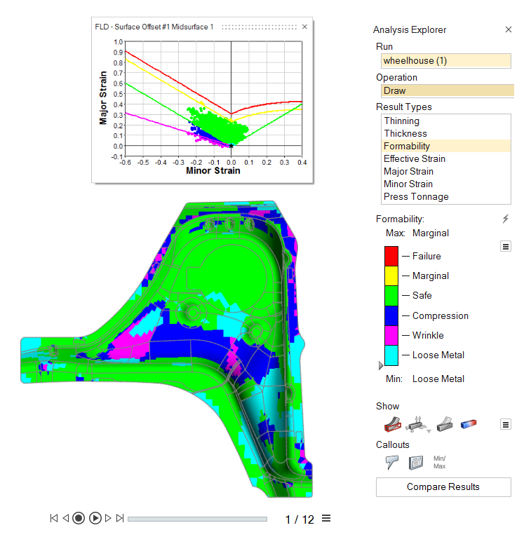
View the analysis results.
- On the Analyze icon, click the Show Analysis
Results tool.

The Analysis Explorer window opens.- To view the blank flattening, on the slider below the model, click the
play button:

. - To check for any failure zones, select the Formability result type.
- On the Analyze icon, click the Show Analysis
Results tool.