Import Additional Data from ASCII File
Import additional data for highlighting and illustration from an ASCII file.
Additional data such as vector objects for highlighting and illustration purposes, shown in the Project View, can be imported from ASCII file by selecting . A dialog will open where the file path and name of the ASCII file to be imported has to be specified.
The format of the file is restricted to the definitions given below. Lines which do not start with a keyword listed below will not be considered. Each layer or object starts with a new line. Individual values have to be separated with a space.
Data Layer
Tip: At least one layer has to be available in order to import data objects.
In case data layers are already defined in the project, objects can be imported also
to these existing layers if the correct layer ID is specified.
| Keyword | Arbitrary Name | ID | Visible (yes or no) |
|---|---|---|---|
| LAYER | “Layer 1” | 0 | y or n |
Note: At least one layer has to be available in order to import data objects. In case data layers is already defined in the project, objects can be imported also to these existing layers if the correct layer ID is specified.
Rectangle Objects
| Keyword | Layer ID | Line Width | Color (RGB) | Filled Mode (yes or no) | Lower- Left Corner (x, y, z) | Upper-Right Corner (x, y, z) |
|---|---|---|---|---|---|---|
| RECTANGLE | 0 | 1 | 255 0 128 | y or n | 0.00 0.00 0.00 | 10.75 10.34 0.00 |
Polygon Objects
| Keyword | Layer ID | Line Width | Color (RGB) | Filled Mode (yes or no) | Number of Definition Points | Definition Points (x, y, z) |
|---|---|---|---|---|---|---|
| POLYGON | 0 | 2 | 255 0 128 | y or n | 4 | -1.75 10.34 1.50 -4.45 ..... |
Polyline Objects
| Keyword | Layer ID | Line Width | Color (RGB) | Number of Definition Points | Definitions Points (x, y, z) |
|---|---|---|---|---|---|
| POLYLINE | 0 | 1 | 255 0 128 | 2 | 3.28 2.00 1.50 4.87 3.45 1.50 |
Circle Objects
| Keyword | Layer ID | Line Width | Color (RGB) | Filled Mode (yes or no) | Lower-Left Corner (x, y, z) | Upper-Right Corner (x, y, z) |
|---|---|---|---|---|---|---|
| RECTANGLE | 0 | 1 | 255 0 128 | y or n | 0.00 0.00 0.00 | 5.00 5.00 0.00 |
Ellipse Object
| Keyword | Layer ID | Line Width | Color (RGB) | Filled Mode (yes or no) | Lower-Left Corner (x, y, z) | Upper-Right Corner (x, y, z) |
|---|---|---|---|---|---|---|
| ELLIPSE | 0 | 2 | 255 0 128 | y or n | 0.00 0.00 1.00 | 10.75 15.34 1.00 |
Text
| Keyword | Layer ID | Font Size | Bold | Italic | Color (RGB) | Definition Point (x, y, z) | Orientation (degree) | Text |
|---|---|---|---|---|---|---|---|---|
| TEXT | 0 | 14 | y | n | 255 0 128 | 0.00 0.00 0.00 | 45 | “Sample Text” |
Tip: For the layer ID an ID of an existing data layer has to be specified. All
coordinates have to be given in the coordinate system of the project, thus in
meters.
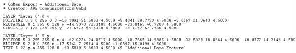
Figure 1. A sample of an import.
Note: In case there a doubts concerning the import format, please define a corresponding
object in CoMan and export it to an ASCII file.