Reflected Rays
Due to the very small distances between the reflecting objects and the concentrated point of radiation, the reflection is only considered correct if the object is significantly larger than the wavelength and larger than the distance between object and center of radiation. This is not valid for most objects (except the wall in the configuration “antenna in front of a wall”). So theoretically the reflections at masts, arms and radomes should not be computed.
But to obtain good and accurate results, the reflections are important. And therefore, they are included in the computation. Reflections at mast and wall are extremely important because the reflection loss is not very high and the signal might have a phase shift of 180° to the direct signal in some directions - which leads to destructive interference and therefore to an elimination of the radiation into this direction. So, the reflections are important and must be considered. Reflections at radomes can be neglected because their attenuation are high and so the superposition to direct paths (without reflections) is nearly invisible in the resulting antenna pattern.
The computation of the reflected ray will be shown in the following example. The ray emitted from P1 will be received by P2, and the reflection at the wall is analyzed.
If more than only one object must be considered, then this step must be repeated for each object.
In a first step, the image of P1 relative to the wall is determined. The distance dPW of the point P1 from the wall is computed with the normal vector nW of the wall.

Figure 1. Scenario for the reflection.

Figure 2. Geometry to compute the reflection.

Figure 3. Image of the transmitter.
If the line from P1A to P2 is intersecting the polygon representing the wall, this point of intersection is named Q and represents the point of reflection.

Figure 4. Computation of reflection point Q.

Figure 5. Computation of angle of reflection at point Q.
The angle of reflection α is determined with:
With the angle α and the material properties of the wall / object the reflection loss can be determined accurately.
This reflection loss is then subtracted from the free space loss given by
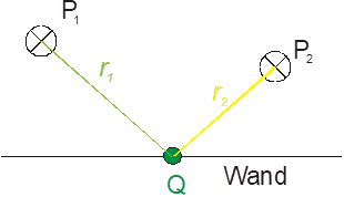
Figure 6. Computation of angle of reflection.
For both parts of the reflected ray (from P1 to Q and from Q to P2), the transmissions / penetrations must be determined additionally.