Section Curves
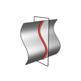
Create an object containing the section curves of a NURBS surface object. You can specify the direction and the position of the section planes as well as the number of the planes and the distance between them. This modeling tool maintains construction history.
-
Click the Section Curves icon.
-
Modify the section curves:
To Do this Note Select a method In the guide bar, select one of the following options: - Method: Custom (default): Define a custom number of section curves by entering the Number of Sections.
- Method: Whole Object: Create as many section curves as can fit on the whole object based on the defined Distance.
Change the number of section curves In the guide bar, enter the Number of Sections. Change the distance between each section curve In the guide bar, enter the Distance. Combine the output In the guide bar, select Combined Output. Move the origin - In the modeling window, drag the Origin point.
- Click the Origin point, and then enter the X, Y, and Z coordinates.
Change the direction - In the Control Panel, select a Reference
Direction:
- Global X Axis

- Global Y Axis

- Global Z Axis

- Reference Geometry: In
the modeling window, click a reference object.

- Custom
 : In the
modeling window, drag the Direction
point, Phi
Angle, Theta
Angle, or Free
Angle, or click one of the arrows and
type an angle.
: In the
modeling window, drag the Direction
point, Phi
Angle, Theta
Angle, or Free
Angle, or click one of the arrows and
type an angle.
- Global X Axis
To invert the current direction, click Invert Direction  .
.