SS-T: 4015 Non-linear Incremental
Review incremental non-linear buckling.
Prerequisites
Some features used in this tutorial are only available in SimSolid Advanced version. Please switch to Advanced to complete this tutorial.
Purpose
In this tutorial, you will do the following:
- Create geometric non-linear analysis.
- Review incremental non-linear buckling results.
Model Description
The following file is needed for this tutorial:
- hinge_beam.x_b
Import Geometry
-
Click the
 (Import from file) icon.
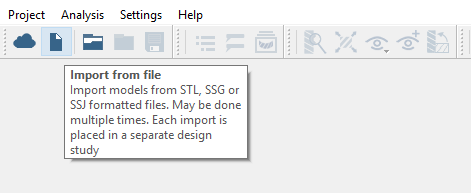
Figure 1.
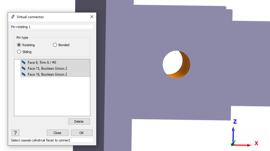
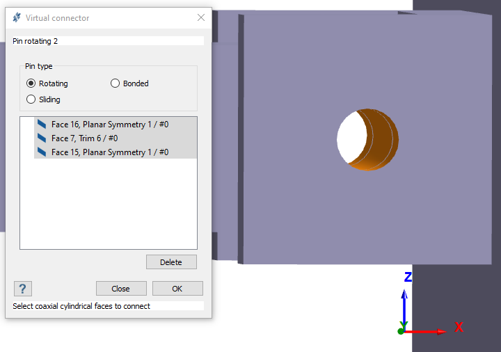
Create Virtual Connectors
Assign Materials
-
In the Assembly workbench, click
 (Apply materials).
Create Structural Non-linear Analysis
-
In the main window toolbar, click
 > Structural non-linear.
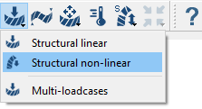
Figure 5. -
For Number of load steps, enter 20.
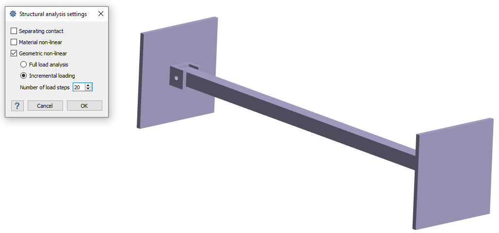 Figure 6.
Create Immovable Support
-
In the Analysis Workbench, click
 (Immovable support).
-
In the modeling window, select the faces shown in Figure 7.
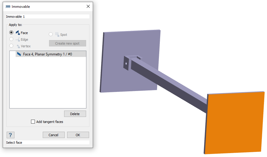
Figure 7.
Create Displacement Load
-
In the Analysis Workbench, select
 > Force/Displacement.
-
In the modeling window, select the faces shown in Figure 8.
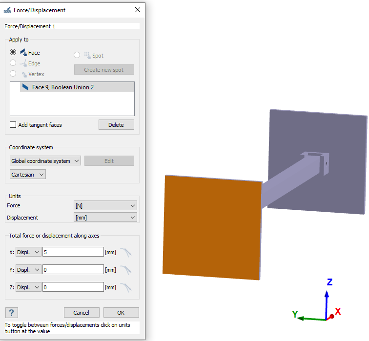
Figure 8.
Run Analysis
-
Click
 (Solve).
A warning about groups of parts connected by sliding contact appears.
(Solve).
A warning about groups of parts connected by sliding contact appears.
Review Results
-
In the Analysis Workbench, select
 > Displacement > Displacement Magnitude.
The Legend and the Load History dialog appear in the modeling window.
> Displacement > Displacement Magnitude.
The Legend and the Load History dialog appear in the modeling window.The load steps where instability occurs are highlighted in red in the Load History dialog. You can click any step to view the deformed shape at the associated load percentage.
-
Click
 (Show history graph) to view a plot of the
displayed response history.
(Show history graph) to view a plot of the
displayed response history.
-
Click
 (Animate history) to animate the load history step
by step.
You can change the speed of the animation by increasing/decreasing the value in the Animation speed box.Note: Make sure the Show deformed shape function is activated when animating the history.
(Animate history) to animate the load history step
by step.
You can change the speed of the animation by increasing/decreasing the value in the Animation speed box.Note: Make sure the Show deformed shape function is activated when animating the history.
View Reaction Forces
-
In the Analysis Workbench, click
 (Reaction/contact force).