SimSolid performs meshless structural
analysis that works on full featured parts and assemblies, is tolerant of
geometric imperfections, and runs in seconds to minutes. In this tutorial,
you will do the following:
Create structural non-linear analysis (material and contact).
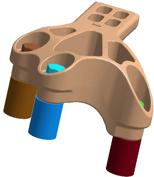
Model Description
The following files are needed for this tutorial:
Material_Separating_NonLinearity.ssp
Stress_strain_curve.csv
Figure 1.
The project file has the following specifications:
Material is set to Aluminum for all parts.
Regular connections with 0.6mm gap and 0.3mm penetration tolerance.
For the sake of analysis, all sliding contacts have been changed to
bonded.
Open Project
Open the SimSolid project file.
Start a new SimSolid session.
Click the (Open Project) icon.
Figure 2.
In the Open project file dialog, choose Material_Separating_NonLinearity.ssp
Click OK.
Define Non-linear Material
Edit the material database to define non-linear material.
In the main menu, click Settings > Material database.
Figure 3.
In the Define material database window, click
Edit current.
Figure 4.
In the dialog, right-click on the Sample non linear
materials folder and select Add Material
from the context menu.
Figure 5.
Select Add stress-strain curve....
Click Edit.
Import the Stress-strain curve.
In the Stress-strain curve window, click
Import CSV.
Figure 6.
In the File explorer, browse to
Stress_strain_curve.csv and click
Open.
In the dialog, click OK.
Figure 7.
In the Edit Material database dialog, you will see
Elasticity Modulus was calculated from the imported Stress-strain curve. Figure 8.
Enter other values in the dialog,
For Poisson's ratio, enter 0.3
For Density, enter 7.85e+03.
For Ultimate tensile stress, enter 0.
For Thermal expansion coeff., enter
1.2e-5.
For Thermal conductivity, enter 5.6e+1.
Edit material name to Steel NL.
Click Apply.
Click Save.
Assign Materials
Apply materials to select parts in the assembly.
In the Project Tree, click on
the Assembly branch.
In the Project Tree, hold down Control and multi-select parts as shown in
Figure 9.
Figure 9.
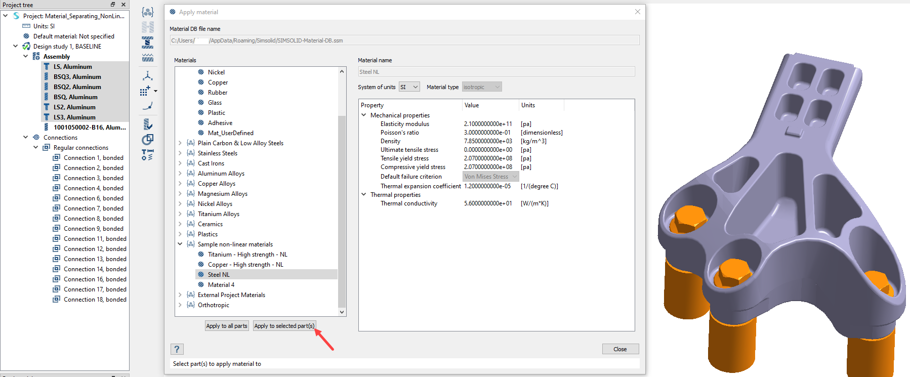
Click (Apply material).
In the dialog, click to expand the Sample non-linear materials
folder.
Pick Steel NL from the list.
Click Apply to selected parts.
Figure 10.
Click OK.
In the Assembly branch of the Project Tree,
material properties are identified for each part.
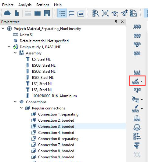
Create Structural Non-linear Analysis
Setup non-linear separating contact and material non-linear subcases.
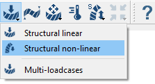
In the main window toolbar, click > Structural non-linear.
Figure 11.
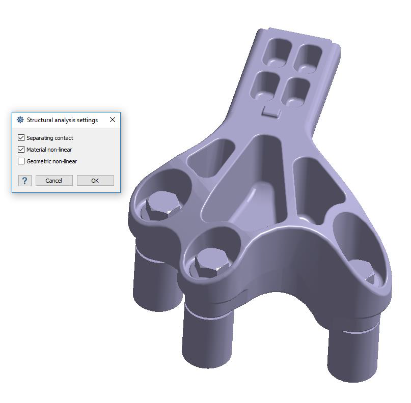
In the dialog, activate the Separating contact and
Material non-linear checkboxes.
Figure 12.
Click OK.
Edit Contact Conditions
Change the contact conditions to separating/closing.
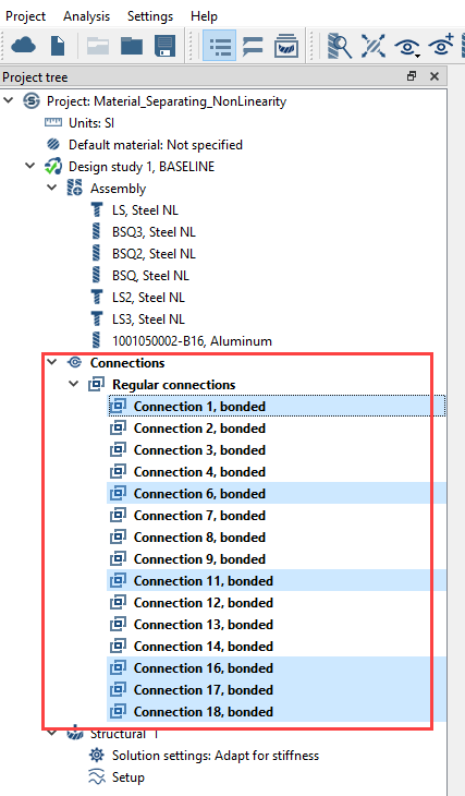
In the Project Tree, expand the
Connections branch.
Hold down Control and
multi-select connections as shown in Figure 13.
Figure 13.
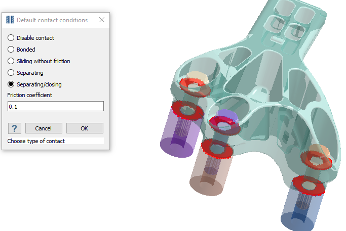
Right-click and select Edit Default contact conditions
from the context menu.
In the dialog, select Separating/closing.
Set Friction coefficient to 0.1.
Click OK.
Figure 14.
Create Immovable Support
Create immovable support.
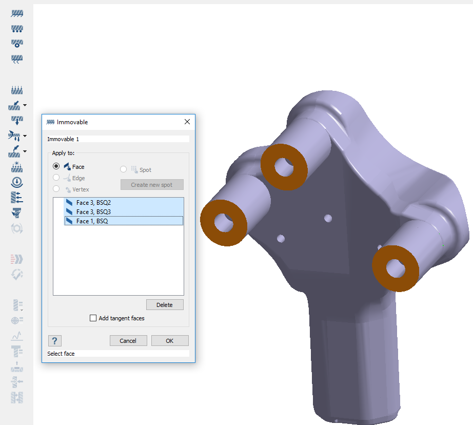
In the Analysis Workbench, click (Immovable support).
In the dialog, verify the Faces radio button is
selected.
In the modeling window, select the faces shown in
orange in Figure 15.
Figure 15.
Click OK.
Tighten Bolts
Create a bolt tightening load.
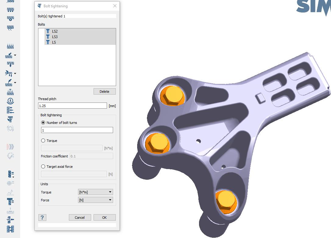
On the Analysis Workbench, select (Bolt tightening).
In the modeling window, select the bolts as shown in
Figure 16.
Figure 16.
For Thread pitch, enter 1.25.
For Number of turns, enter 1.
Click OK.
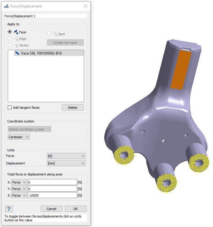
Define Load
Apply Force load.
In the workbench toolbar, select > Force/Displacement.
 (Open Project) icon.
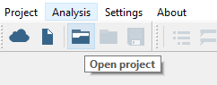
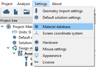
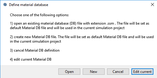
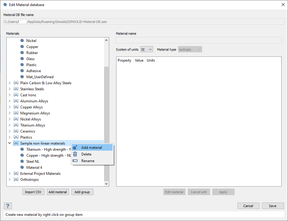
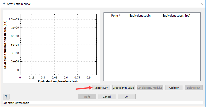
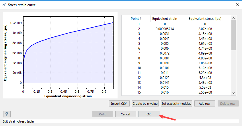
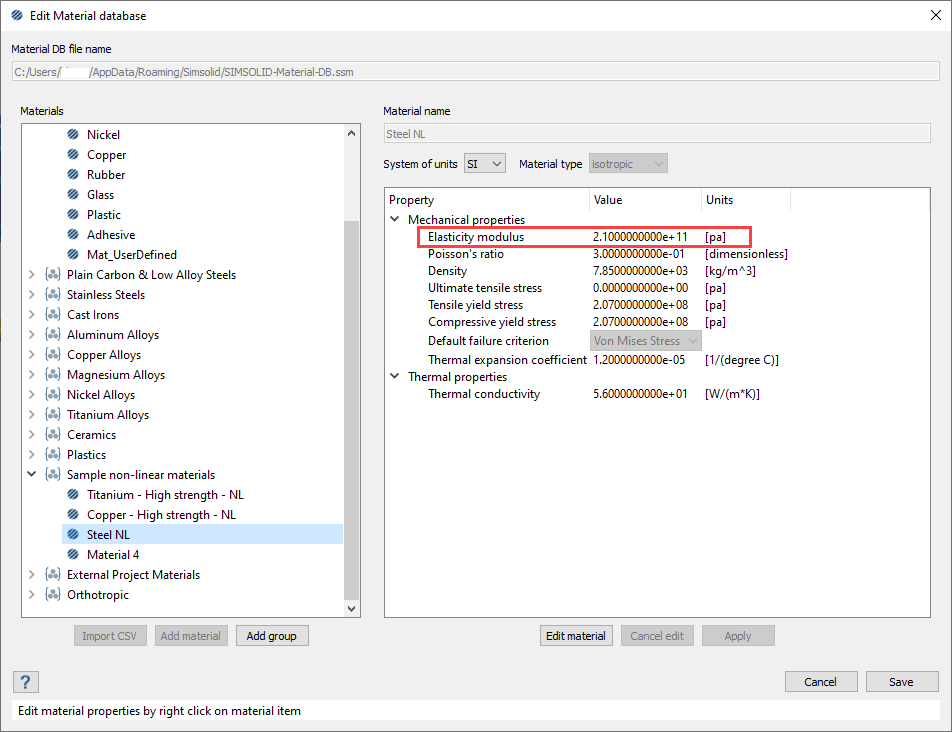
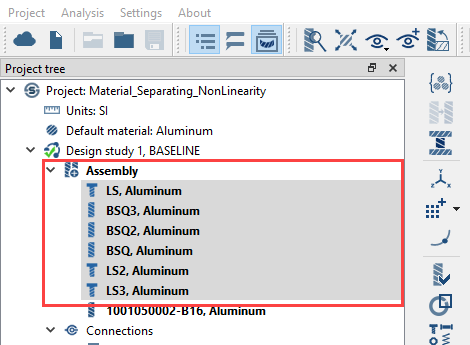 Figure 9.
  (Apply material).
 to expand the Sample non-linear materials
folder.
to expand the Sample non-linear materials
folder.
 > Structural non-linear.
 (Immovable support).
 (Bolt tightening).
 > Force/Displacement.
 (Solve).
 (Results plot) icon.
 (Bolt/Nut resultant forces).
The Bolt/nut forces dialog will display.
(Bolt/Nut resultant forces).
The Bolt/nut forces dialog will display. (Contact response).
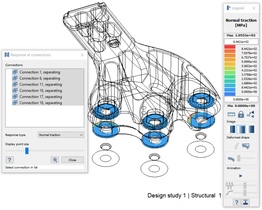 Figure 19.