SS-T: 4020 Modal Analysis, Bridge
Use modal analysis to calculate the first 3 flexible modes of a bridge assembly.
Purpose
SimSolid performs meshless structural
analysis that works on full featured parts and assemblies, is tolerant of
geometric imperfections, and runs in seconds to minutes. In this tutorial,
you will do the following:
- Learn the SimSolid workflow.
- Create modal analysis to calculate flexible modes.
Model Description
The model used in this tutorial is a 30-part bridge assembly.
The following model file is needed for this tutorial:
- bridge.stl
- bridge.ssp
Import Geometry
-
Click the
 (Import from file) icon.
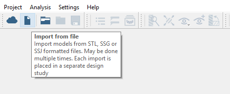
Figure 1.
Create Connections
Specify gap and penetration tolerances to create automatic connections.
-
In the Connections workbench toolbar, click
 (Automatic connections).
Assign Materials
-
In the Assembly workbench, click
 (Apply materials).
Create Modal Analysis
-
On the main window toolbar, click the
 (Modal analysis) icon.
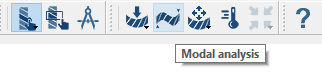
Figure 2.
Run Analysis
Solve the analysis.
- In the Project Tree, open the Analysis Workbench.
-
Click
 (Solve).
Calculate Flexible Modes
Calculate the first three flexible modes.
-
Plot the Displacement magnitude contour.
-
On the Analysis workbench toolbar, click the
 (Results plot) icon.
- In the menu, select Displacement magnitude.
The Lengend window will appear showing the contour plot. A Frequency window will also open. -
On the Analysis workbench toolbar, click the
-
Calculate the first three flexible modes.
- In the Frequency [Hz] window, select the seventh frequency in the list.
-
In the Legend window, pick the
 (Show deformed shape) icon.
-
Click the
 button to animate the mode shape.