Automatically Create Runner System
If your model geometry does not include a runner system, you can create a virtual runner system automatically with the Create Runner tool.
Location: Molding tab,
Runner System secondary ribbon

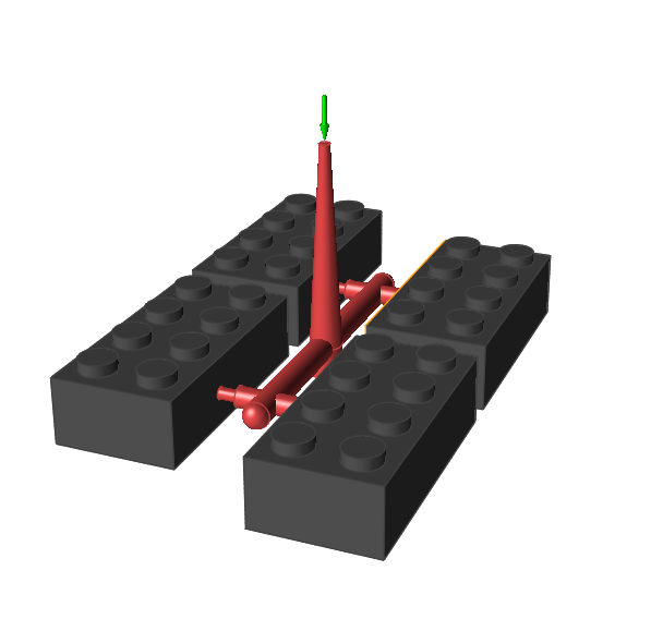
After you define the required number of part cavities for your model, use the
Create Runner tool to generate the entire runner system for the model including the
gate, runner, sprue and injection point.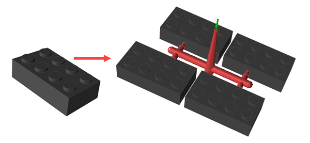
-
Click the Runner System icon.

-
Click the Create Runner icon on the secondary ribbon.

-
Enter the parameters for your part(s) and runner system on the Create Runner
dialog.
Parameter Description No Cavities Enter the number of part cavities to fill. Keep the default of 1 or enter increments: 2, 4, 8, 16 or 32. Cross Section Select Circular or Square for the shape of the runner. 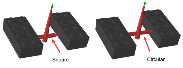
Initial Runner Radius or
Initial Runner Width and Height
Define the cross section for the runner segment that initially attaches to the sprue. If you selected a circular cross section, enter its radius. If you selected a square cross section, enter its width and height. 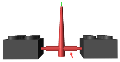
Sprue Height Enter the height of the sprue. 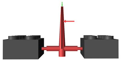
Sprue Puller Depth Enter the sprue puller depth. 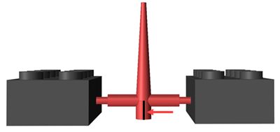
Runner Depth Enter the runner depth. 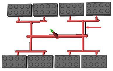
Runner Final Section Depth Enter the depth of the runner section that attaches to the gate. 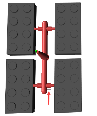
Parts Separation Enter the distance between parts. 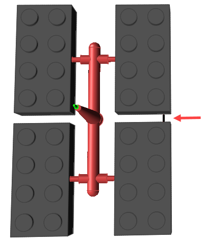
-
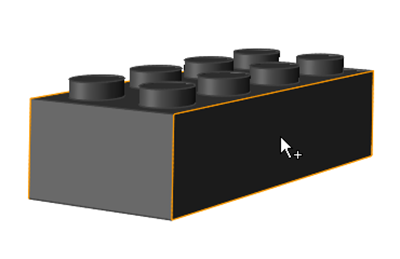
Select a surface of the part where you want to attach the gate of the runner
system.
Note: If your part already includes a designated gate, you do not need to select a surface. The runner will automatically attach to the existing gate.
The software automatically generates the runner system for your model.